It has been some time since our last C&NW 1385 status update. Upon delivery of the boiler, a few photos were posted with the promise of more to come, but as Mid-Continent entered our busy special event season the sharing of additional photos and videos got put off by more pressing projects. However, that doesn’t mean work halted on the 1385. Now that the busy 2019 season is behind us, we’ve had a chance to put together this mega-update for you.
Boiler Delivery
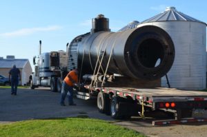
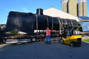
C&NW 1385’s boiler has represented the single most challenging part of the locomotives rebuild. Planning of the boiler was started early in the rebuild process and in-depth engineering work started in 2015. The construction contract was signed with Continental Fabricators in late 2016. Many design iterations went back and forth as the project volunteers, boiler engineer, and manufacturer exchanged ideas and tweaked components. Finally, by late September 2019 the boiler was ready to ship, arriving on September 26, 2019. The following photos explain the activities.
In addition to still photos, a series of GoPro cameras mounted on the locomotive, a tripod camera, and a drone were all on hand leaving no angle uncovered. The following photos and video are courtesy Jeffrey Lentz and Randy Long. Update text by Peet Deets and Jeffrey Lentz.
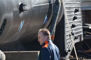
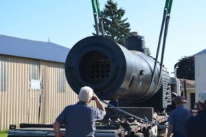
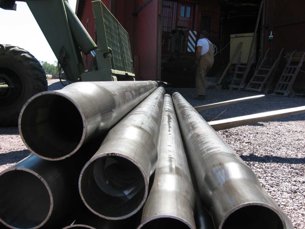
After departing the previous day from St. Louis and arriving at SPEC Machine in the middle of the night, 1385’s boiler is prepped for unloading. Although paling in size to some locomotives, the 1385 is hardly small – seen here dwarfing SPEC Machine’s forklift being used to unload spare boiler tubes from the trailer. As hinted at by the photo backgrounds, SPEC Machine is not normally a locomotive heavy repair shop and is actually located on a working farm.
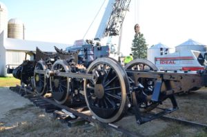 1385’s running gear was pre-positioned outside on temporary track in order to receive the boiler.
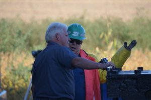
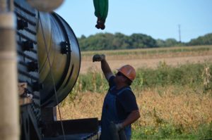
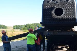
LEFT: SPEC Machine owner, Steve R., talks unloading strategy with 1385 Task Force volunteer Pete D. (in hard hat). CENTER: Mid-Continent volunteer Ed R. gets ready to attach the crane’s lifting straps to the 1385 boiler. RIGHT: Brett M., the engineer of the new boiler, is on hand to help with the boiler lift and make sure everything goes smoothly.
The new boiler is gently lifted off the trailer as SPEC Machine’s Steve R. looks on.
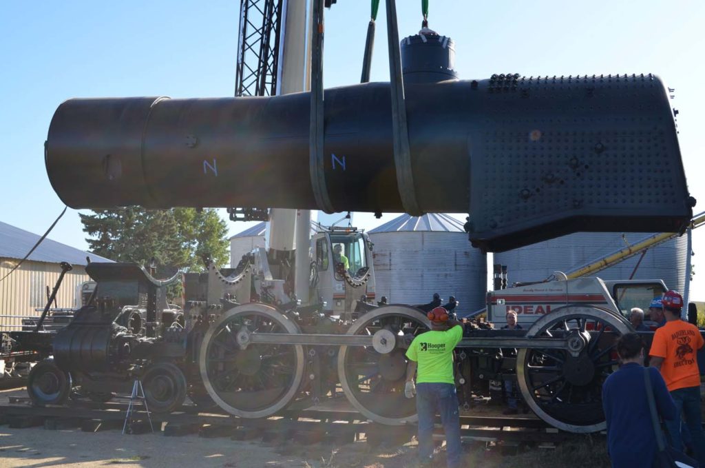 In short order, the boiler has been positioned over the locomotive’s running gear and has started being lowered.
 SPEC Machine’s Tyler R. keeps hold of a tether attached to the boiler. Wind speeds picked up as the lift was underway, causing the boiler to want to sway and swivel. The tether straps permit control over the lift without risk of getting fingers or hands pinched by the 41,000 lb boiler.
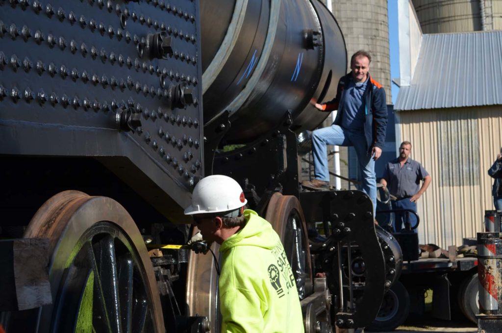 Despite the large size of the equipment involved, it is a game of fractions of an inch when it comes to placing all the pieces together. Here 1385 Task Force member Mike W. is seen taking a tape measure reading as they battle a bit of a breeze while trying to set the boiler on the exact spot needed.
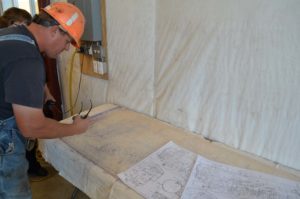
LEFT: Some components couldn’t be fabricated until after the boiler was fitted and tolerances defined. In the meantime, timbers are used to support the boiler on the firebox end. CENTER: Ed R. verifies boiler placement against blueprints from the Chicago & North Western railroad. RIGHT: The increasing wind level made positioning the boiler on the exact centerline of the frame increasingly difficult. A speed square is pulled out to verify the accuracy of the last attempt.
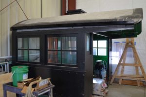
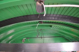
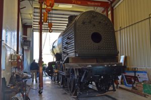
1385’s boiler is Inside SPEC Machine’s shop, waiting on other parts of the locomotive to catch up before the cab can be installed. Since previous updates, the roof has been covered and rain gutters installed. Inside the cab the wiring for various electrical systems have been installed.
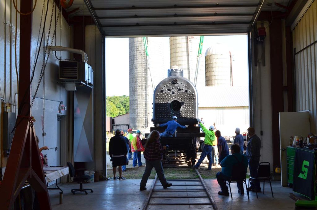 Boiler placement continues to be adjusted as friends and family members look on from inside the shop.
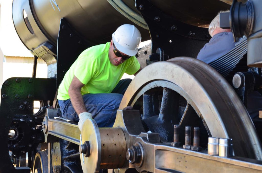 One of the boiler supports was discovered to be positioned slightly too high causing the boiler to sit unevenly. Adjustments are quickly made by Mike W. and Steve R.
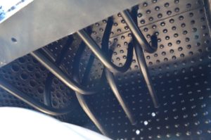
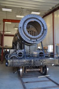
With the ash pan and grates not yet installed, this view looking up into the firebox was possible, showing the arch tubes which help circulate water around the firebox walls.
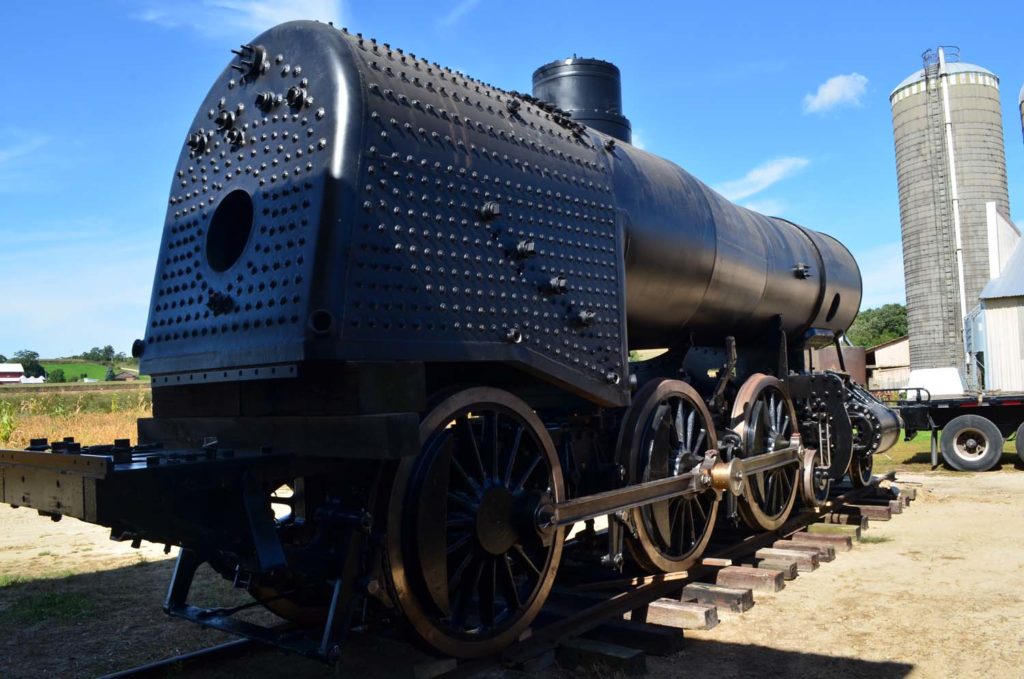 After a bit of struggle fighting the wind, the crew was finally able to get the boiler placement just right and the crane was able to set it down.
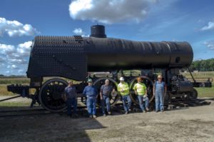
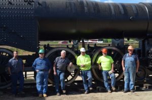
Key members of the 1385 crew gather for a group photo to celebrate the completion of a major step in the 1385’s journey toward operation. From left to right, Tyler R., Pete D., Steve R., Mike W. Tim K., and Ed R.
After the boiler was placed and a lunch break enjoyed, a tractor was used to tow 1385 inside the shop bay where work will continue.
Progress Since the Boiler Delivery
In the time since the boiler was delivered work has continued on the hundreds of to-do list items that need to be checked off before the locomotive assembly can be completed. These tasks are less attention-getting than a new boiler, but no less important to the locomotive’s rebuild.
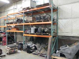
In November 2019, a MCRM members work session was held to help organize the thousands of parts and pieces associated with the locomotive. The palette racking set up during the Member’s work session is being put to good use. As seen here, the racking has tripled the amount of usable space for storage in that spot.
Progress has been made on items that will go both inside and outside the new boiler. Here is the air-operated firedoor that is the target of every fireman. The 1385 is a hand-fired coal-burning locomotive so every shovel full of coal passes through this door. The control valve, cylinder and piston have been rebuilt so the door was able to open itself for the first time in over 20 years.
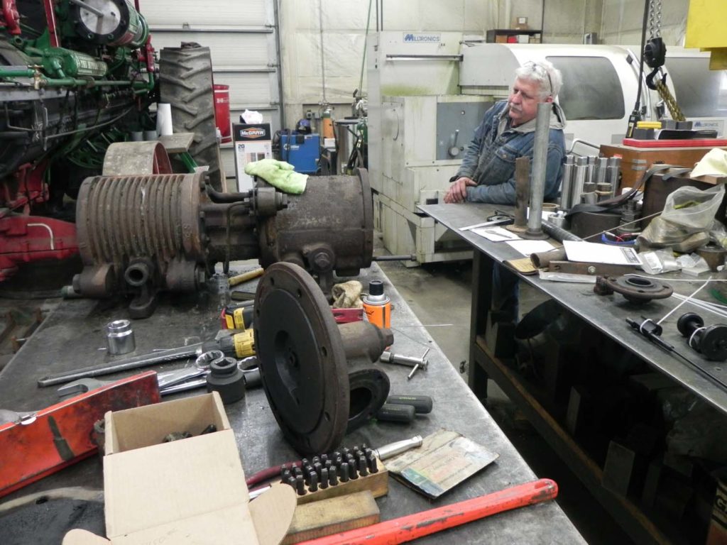
SPEC Machine’s Steve R. is explaining the disassembly of one of the two steam-driven air compressors that supply air for the braking system and other appliances of the 1385. Both compressors will be torn down for inspection and necessary repair. After rebuilding they must be tested to Federal Railroad Administration specification in order to prove they can deliver enough compressed air for safe train operation.
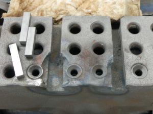
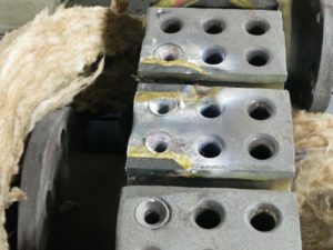
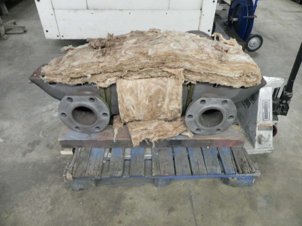
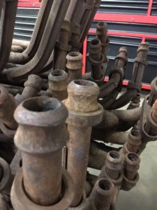
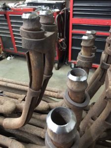
Here is a shot of what is actually the bottom of the superheater header. As you can see the years have not been kind to the header and some pieces have been broken out. It was found that the header was weldable so the small blocks shown were welded in to replace that material that had been chipped out. The area to be repaired must be pre-heated to several hundred degrees Fahrenheit and will be covered with insulation afterward so it will cool very slowly to prevent cracking. The second photo shows the bottom of the superheater header after the welded repair. After a bit more cleanup the sockets seen in the surface will be cleaned up by machining so they will be ready to accept the superheater units and be clamped to a steam tight joint.
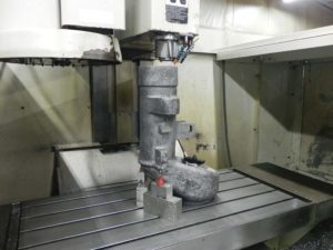
- IMAGE 2: The throttle has its bottom sealing surface machined. The throttle is positioned upside-down in this image.
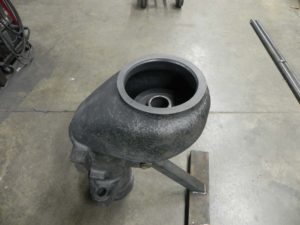
- IMAGE 2: 1385’s throttle (top view).
This is the throttle body that normally resides inside the steam dome and is used to control the amount of steam getting to the cylinders. In the first photo it is upside down in the large milling machine so one of the surfaces that connects to the dry pipe can be cleaned up and made steam tight. A leak at that end of the throttle body would allow a constant flow of steam into the cylinders that could not be controlled.
The second photo shows the throttle body as it will sit in the steam dome. The throttle spool will fit down into the large opening and when the throttle is shut the top of the spool will rest on the upper edge of the opening where you can see the small beveled edge. The bottom side of the spool will rest against a similar sealing edge inside the body to create the steam tight seal of a closed throttle.
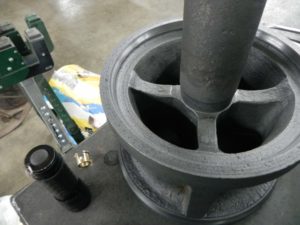
- IMAGE 3: Detail view of the bottom of the throttle. This is the end that will connect to the dry pipe.
The first photo above is of the throttle spool sitting upside down on the bench. The shiny edge just inside the ring of the spool closest to the camera will contact the sealing surface inside the throttle body. The shiny edge at the table will contact the surface at the top of the throttle body.
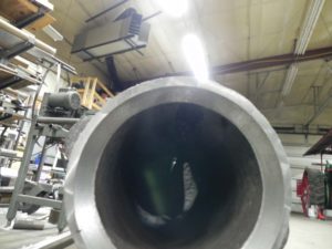
The second photo shows the sealing surface at the bottom-most end of the throttle body where the body will connect to the dry pipe. This is the surface that was getting machined in the picture of the body in the milling machine.
This is the superheater header wrapped in insulation to allow it to slowly cool after the repair welding. The superheater eventually will be installed inside the smokebox at the front of the boiler. The two large flanges seen in the photo connect to the branch pipes that carry the superheated steam down to the valves and cylinders which then turn the driving wheels.
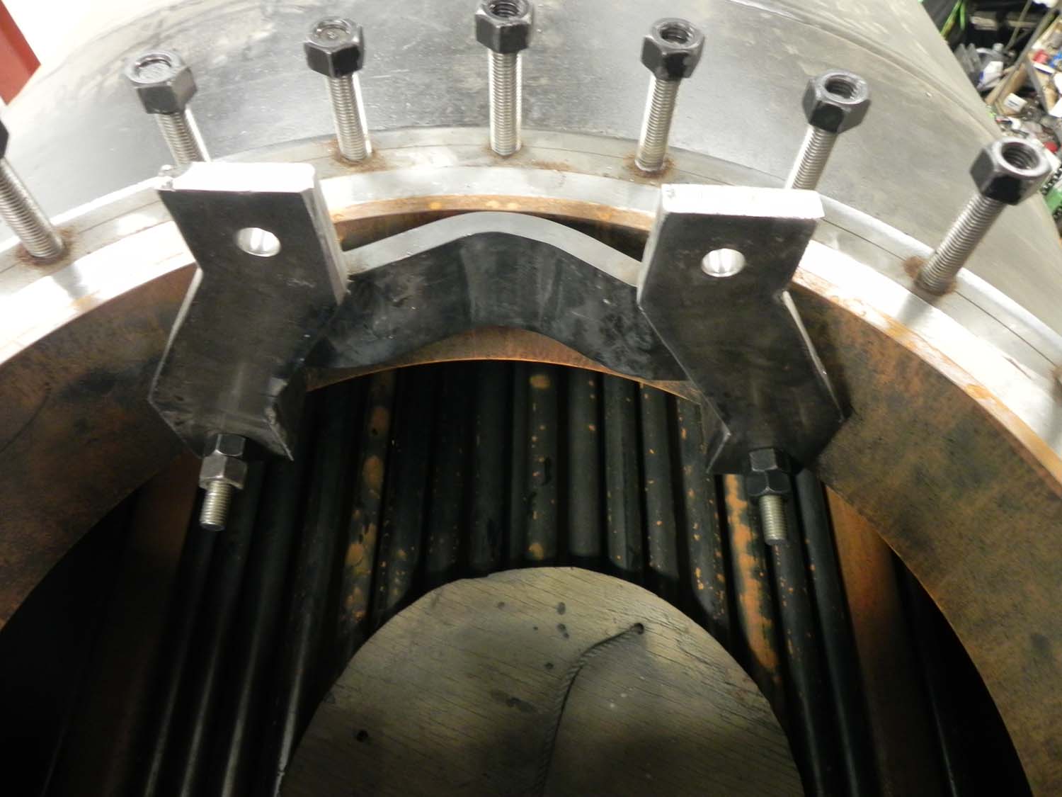
This is the bracket mounted inside the steam dome at the top of the boiler that will hold the throttle body. The fire tubes and a couple of superheater flues are visible inside the boiler.
This is the throttle body (now attached to the bracket from the previous photo) and looking at the sealing surfaces for the spool. The shaft of the throttle spool will drop down through the hole in the center of the body.
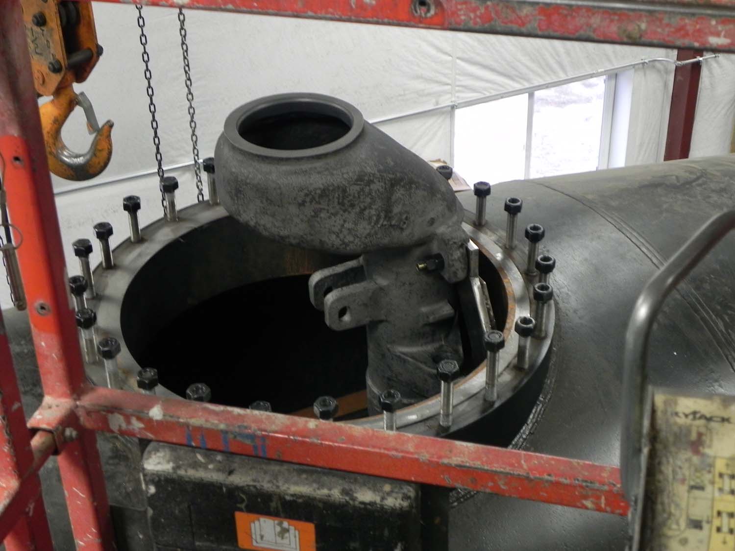
A different view of the throttle body mounted to the bracket and edge of the steam dome. The front of the locomotive is to the right and the backhead, cab and crew would be to the left. Differing from the old boiler, the new boiler has a removable steam dome and the dome ring has been pulled off to accommodate this fitting work. When re-installed, the ring will extend well above the throttle so the dome lid can be properly installed.
Lastly, we have a before and after picture of the ball ends of the superheater units. Before cleanup you can see how rough they became through use and storage. The ends now have a freshly polished sealing surface.ange.
Thank you for your patience with our delays getting this update created. We’re looking forward to a productive 2020!
Please remember that while we appreciate the public’s enthusiasm to see 1385’s progress, the contractor shop where the 1385 work is taking place is a private business, not a museum. They are not open for public tours. Any persons without prior authorization showing up at their shop hoping to see the 1385 will be turned away. If you wish to partake in future 1385 volunteer work sessions, consider joining Mid-Continent as a member.

