Mid-Continent Railway MuseumPosted on by Jeffrey Lentz
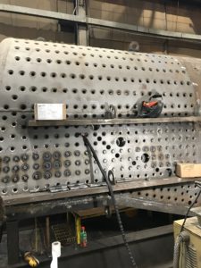
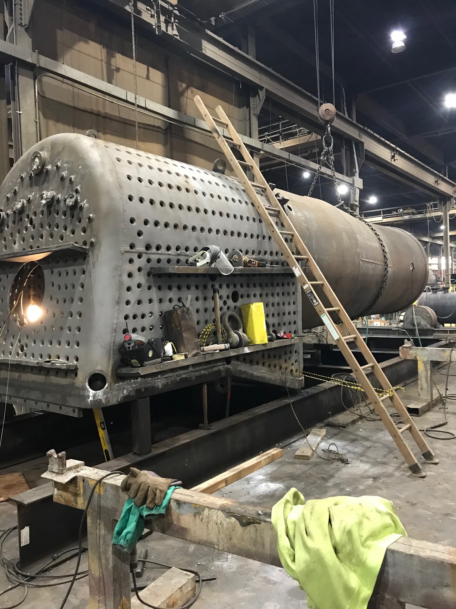
Tom G. of Continental Fabricators kindly supplied Mid-Continent Railway Museum with this photo of C&NW 1385’s boiler. The photo was taken on April 17, 2019, and shows the boiler barrel in position as it is readied to be joined to the firebox. Work on the boiler is taking place at the Continental Fabricator’s shop in St. Louis, Missouri. When completed, the boiler will be delivered to Wisconsin and be set on the C&NW 1385’s overhauled frame.
Mid-Continent Railway MuseumPosted on by Jeffrey Lentz
Our previous post provided a tour of the Continental Fabricators facility where the brand new boiler C&NW #1385 boiler is being constructed. In this post, 1385 Task Force member Pete Deets shares his photos taken of the 1385 boiler during their shop tour in late February.
At the end of the previous post, I thought I spied something familiar. Could it be our own beloved R-1 in the distance?
Pete Deets Photo.
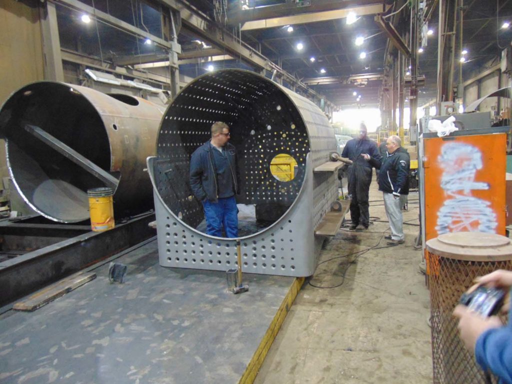
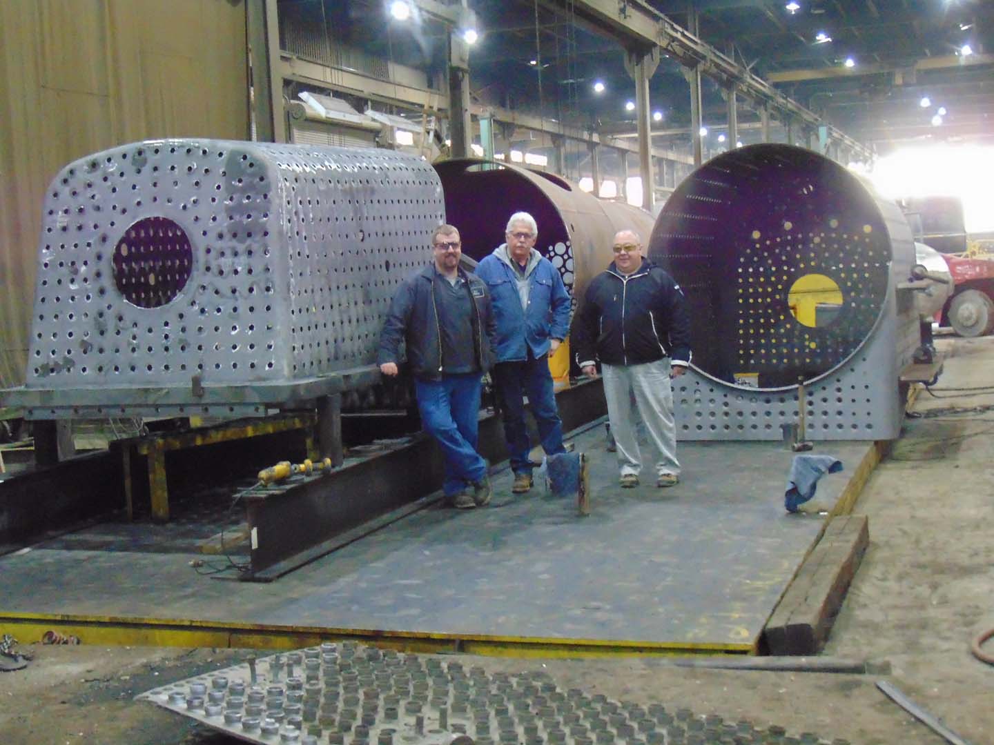
Indeed, here are the pieces of the new vessel.
Pete Deets Photo.
This is actually an assembly table embedded in the shop floor which gives the boilermakers a stable, flat surface to work from. The mudring/firebox assembly is mounted to standoffs on the I beams and is set up to be level and square. With the foundation ring level and square the rest of the boiler assembly can be indexed off that so there won’t be twists and turns where we don’t want them. The boiler barrel courses/smokebox assembly is on the I beams ahead of the firebox. In the photo above Tyler R. of SPEC Machine inspects the wrapper assembly. In the photo below Tyler and Steve R. talk over the boiler with Tom G. of Continental.
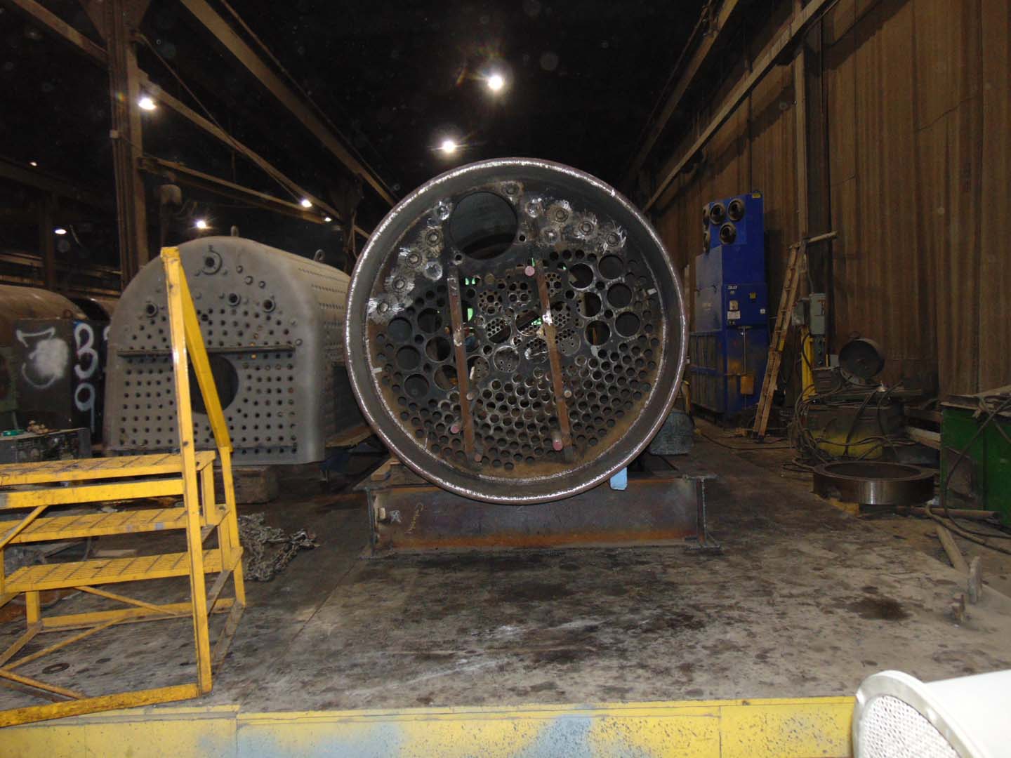
Pete Deets Photo.
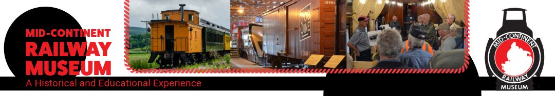
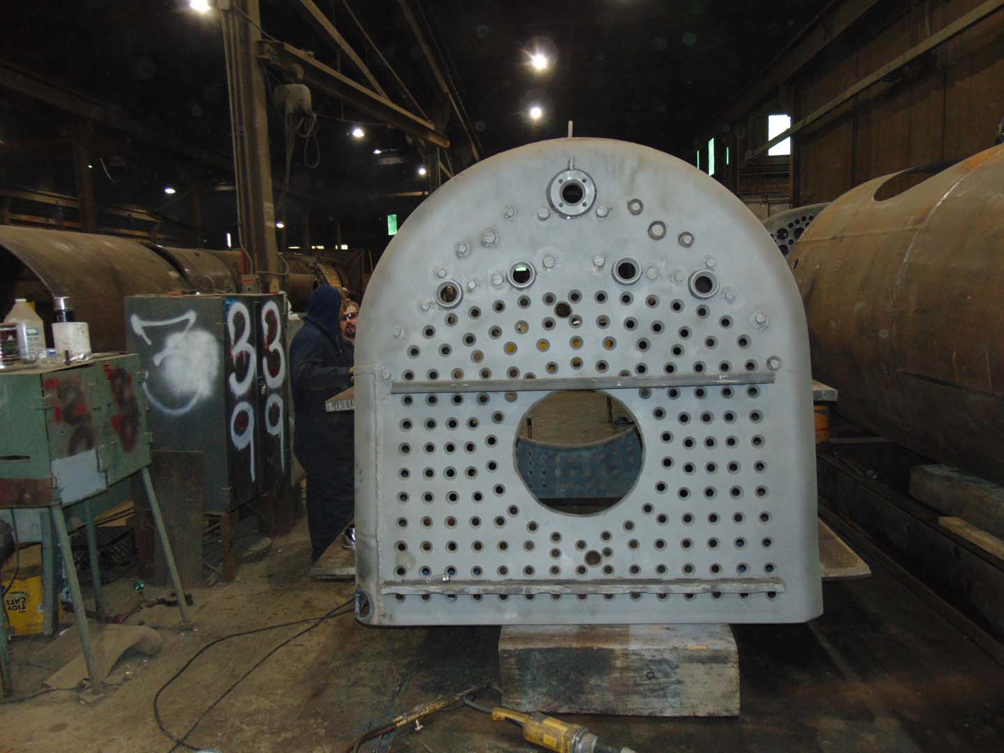
From the other side of the assembly table we’re looking into the smokebox at the front tubesheet with the firebox assembly setting beside it. The small holes are 2-inch diameter for the tubes and the larger holes are 5 inches for the superheater flues. The largest hole is for the dry pipe which will carry the steam from the throttle inside the steam dome of the boiler into the superheater header which lives in the smokebox. After traveling through the superheater units the steam will leave the high temperature side of the superheater header and head down the branch pipes to the valves and cylinders to make everything move.
Pete Deets Photo.
The above picture is looking through the dry pipe hole at the rear tubesheet on the firebox assembly. It won’t be too long before these are joined together.
Pete Deets Photo.
Here is a good look at the backhead portion of the wrapper assembly. You can see temporary “strongback” braces that are welded on here as on many of the other parts. These are to minimize warping from the heat of the welding process and are used to keep flat sheets flat and round pieces round.
Pete Deets Photo.
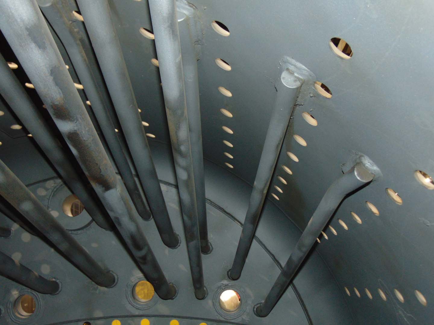
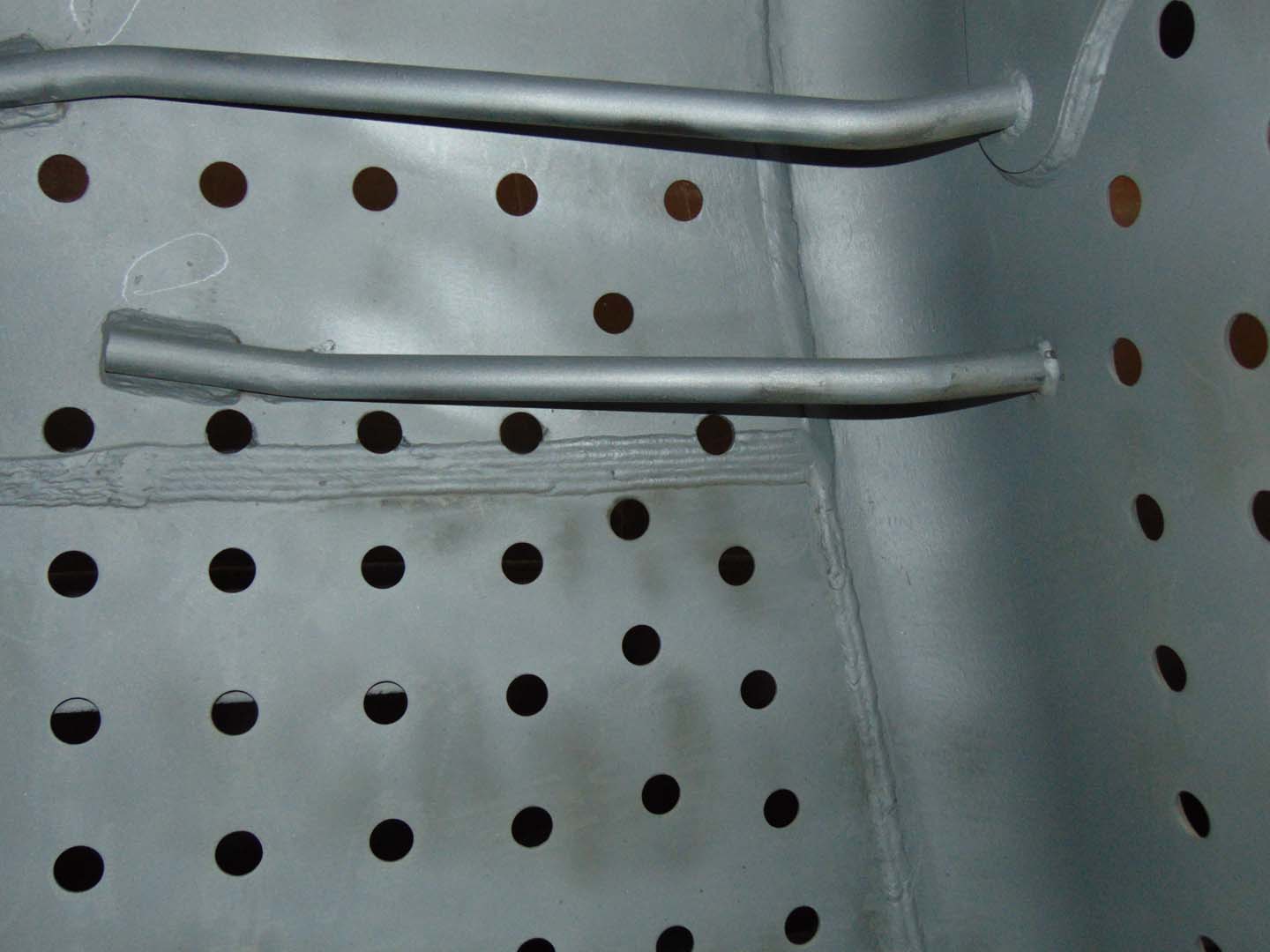
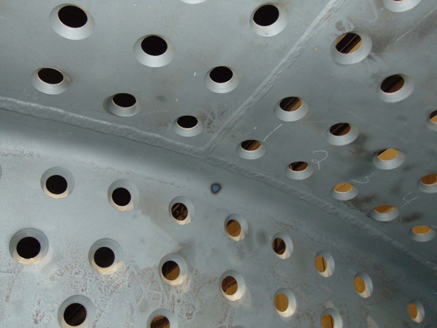
This is a look inside the wrapper assembly at the permanent braces that are attached between the wrapper shell and the backhead. The Continental staff spent several weeks laying out and fitting the braces because there will be staybolts installed in every one of the small holes in the wrapper. The stays will tie the firebox and wrapper sheet together as the steam inside tries to push them apart. There must be a specified clearance or space between the braces and staybolts so they can’t rub.
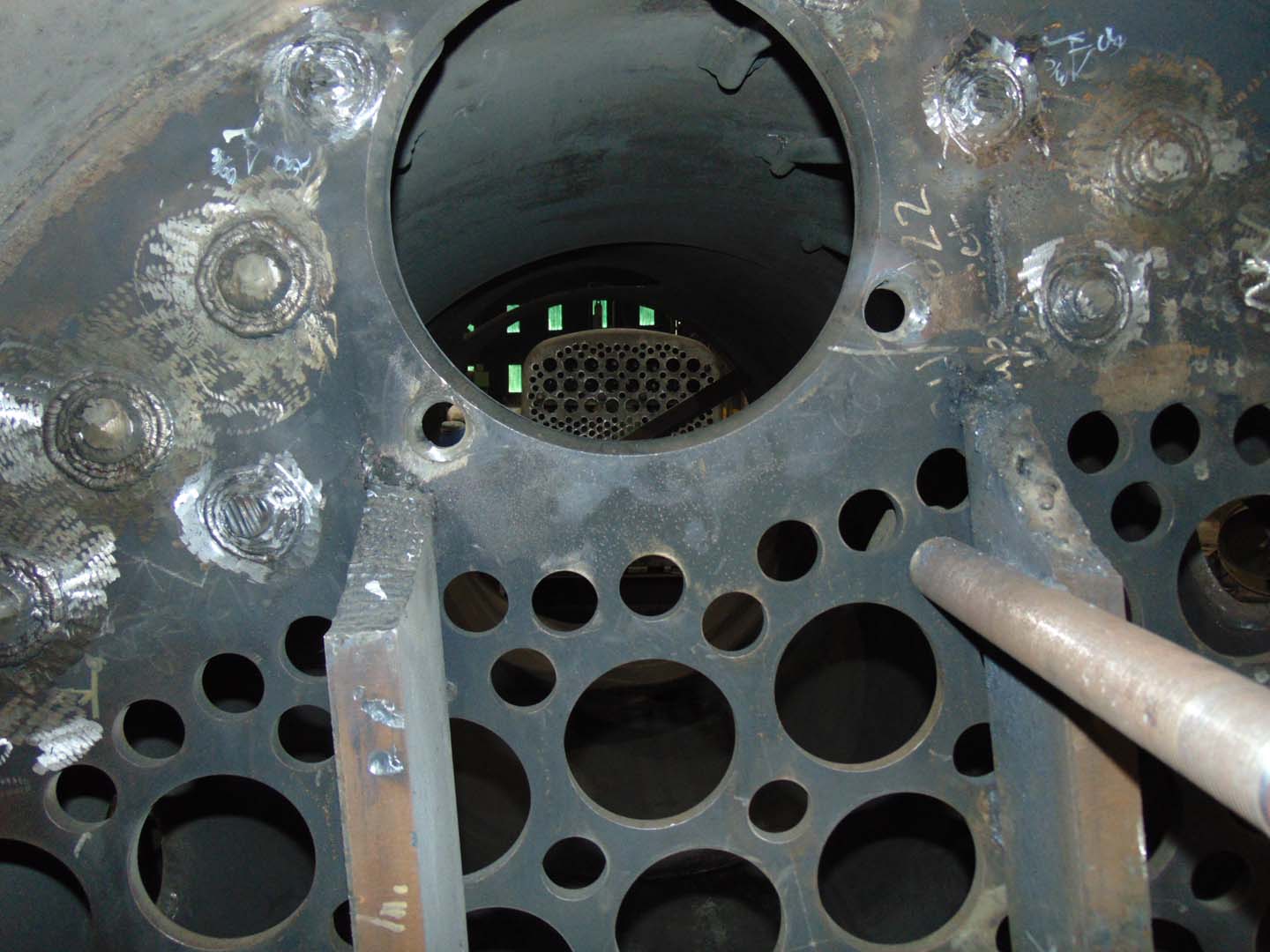
Pete Deets Photo.
Here is a closer look at a pair of stays that required a slight bit of adjustment.
Pete Deets Photo.
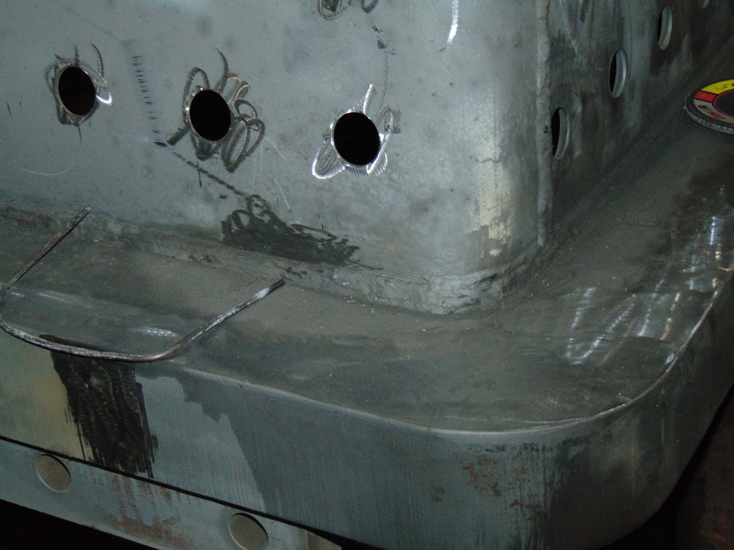
This is a look at one corner of the mudring/firebox. The tab at the left of the photo is tacked in place to help locate the wrapper as it is lowered onto the mudring. The U-shaped pieces of wire will be used as spacers between the wrapper and mudring to maintain the required gap between them as part of the full penetration welding process. The written welding procedure states a specified gap must be maintained between the parts and that gap is filled with the welding rod in what is called the “root pass” of the weld. The wrapper will first be tacked into place with several small welds and the spacers will then be removed to allow the procedure to continue.
Pete Deets Photo.
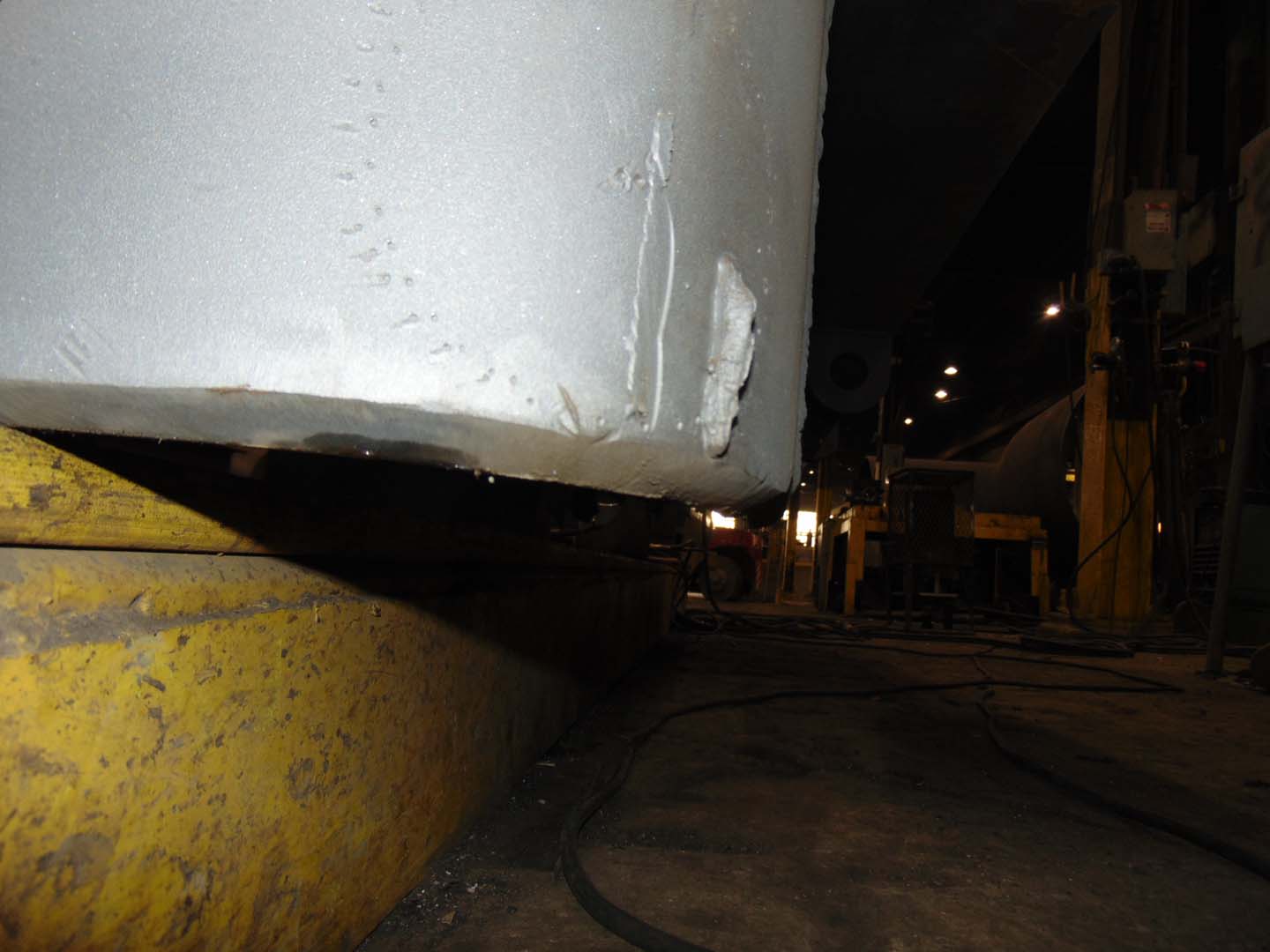
Here is a little closer look at the finished full penetration weld joining the firebox to the mudring.
Pete Deets Photo.
This is the bottom of the wrapper assembly where it will be welded to the mudring. The edge is ground off at an angle or beveled to allow the welder to reach to the very inside edge of where the wrapper and mudring will meet. This is vital to allow the “root pass” to join the innermost surfaces of the wrapper to the mudring and then layers of weld will be built up on top of the root to the full thickness of the wrapper sheet. This way the joint between the pieces can be considered as strong as the pieces that are joined together.
Pete Deets Photo.
This is looking up at the center rear of the top of the inside of the firebox. The 2 pieces of the firebox join the door sheet and the weld line runs down the centerline of the boiler. You can also see how the staybolt holes are beveled like the bottom of the wrapper was to allow for the full penetration weld.
Pete Deets Photo.
Here’s one last shot of Tyler, Steve & Tom.
A few days after the visit, Tom from Continental Fabricator’s sent over a photo he took on March 4th showing further progress on the firebox/wrapper assembly.
Mid-Continent Railway MuseumPosted on by Jeffrey Lentz
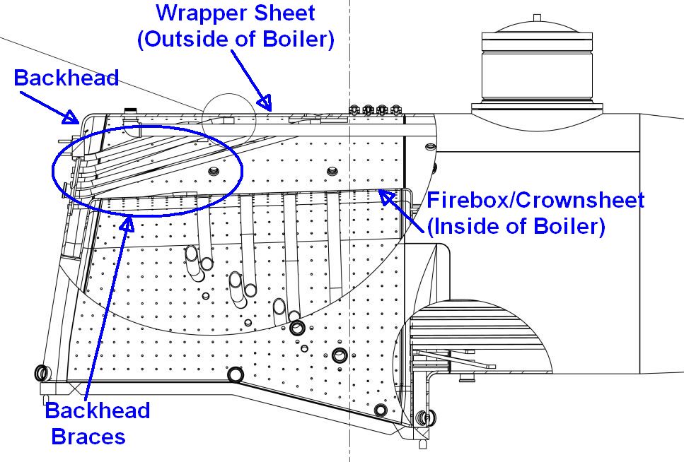
During the last week of January Continental Fabricators began installation of the 1385’s backhead diagonal braces. The backhead is the end of the boiler located within the cab and is a large, flat plate or sheet of steel that has been flanged and then welded to the wrapper sheet. Flanging is the process of very carefully curling the edges of a sheet to meet the next piece it will be mated to. The flanging process has been covered in previous update posts.
Much of the boiler is round, a naturally strong shape. With areas that are flat or nearly flat the forces of nature (including steam pressure) are constantly trying to force them round and thus they require support or “staying”. Staybolts, or “stays” and braces are thus used to reinforce the area and prevent the backhead as well as the other flat areas from bowing outward when the boiler is under pressure.
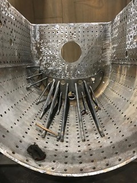
While installing these braces, crews at Continental Fabricators flipped the wrapper sheet/backhead assembly upside-down to facilitate easier working conditions. The first photo below shows the assembly as of the last week of January 2019 as the braces are being fitted and tack welded in place. The tack welds are just enough to hold the braces in place so this assembly can be righted and lowered onto the firebox/mud ring assembly to check for proper clearance between the braces and the firebox. Once Continental is satisfied with the fit-up between the pieces the wrapper assembly will once again be pulled off the firebox, inverted and the braces will receive the final welds.
Much of the backhead will be supported via staybolts connected between it and the firebox door sheet. The pictured diagonal braces are used to support the part of the backhead that does not line up with the door sheet and is instead connected to the wrapper sheet for support. This picture was taken during the last week of Jan. 2019. Photo courtesy Continental Fabricators.
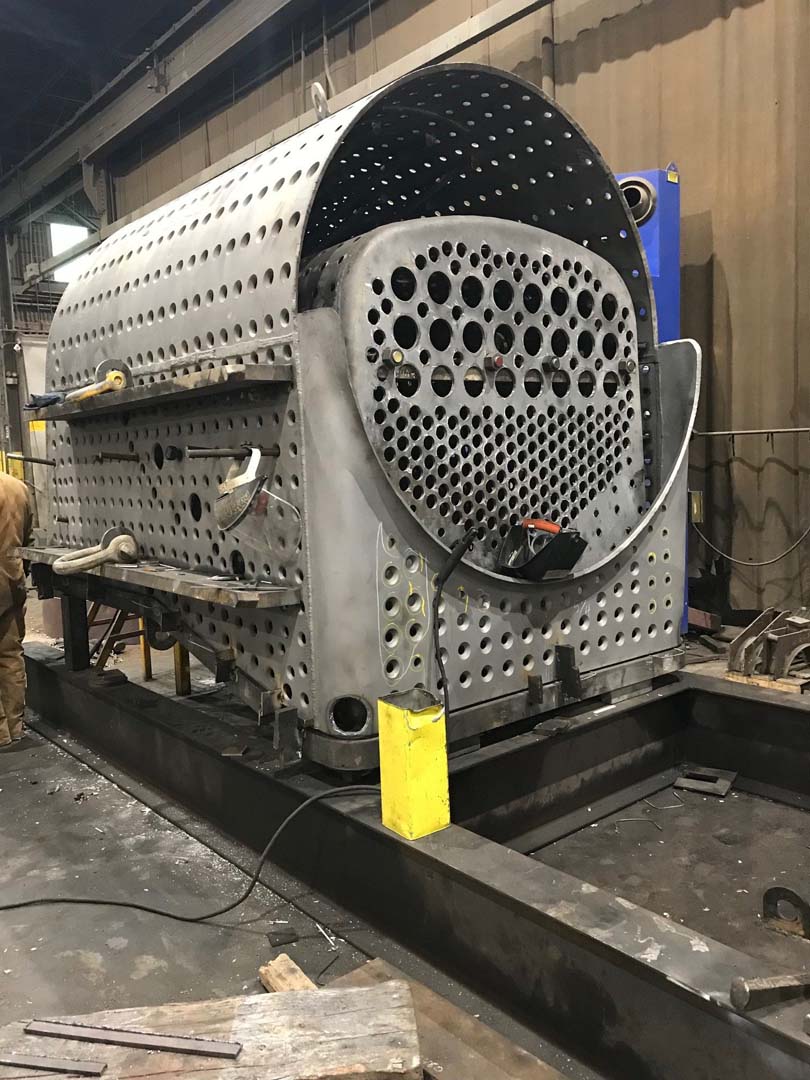
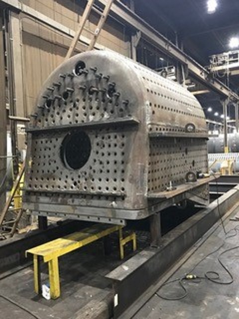
A few days later during this the first full week of February, Continental’s crews had flipped the backhead/wrapper sheet assembly right-side-up again and placed it over top the firebox/mud ring assembly. The purpose of doing this is to test fit for any contact between the backhead braces and the firebox crown sheet before final welding of the braces and before the wrapper sheet/backhead assembly is welded to the firebox/mud ring assembly. Once the two assemblies become one the installation of the staybolts can begin.
Test fitting the wrapper for proper clearance before completing backhead stay installation. Photo courtesy Continental Fabricators.
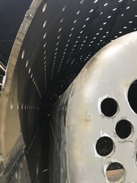
This photo was taken from the front of the firebox looking toward the backhead. It shows the steam/water space between the firebox/crownsheet and the wrapper sheet. Photo courtesy Continental Fabricators.
Mid-Continent Railway MuseumPosted on by Jeffrey Lentz
The following is an update on C&NW #1385’s new boiler progress comes courtesy of Continental Fabricators. Continental is the company creating the new boiler for the 1385.
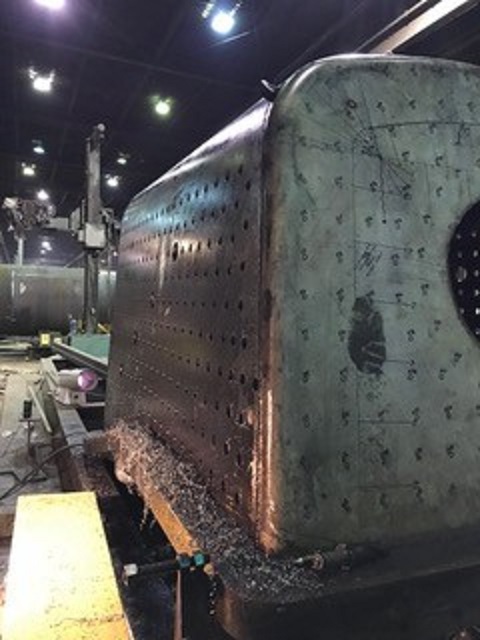
The wrapper sheet has been removed and welding is complete except for the wash out plugs.
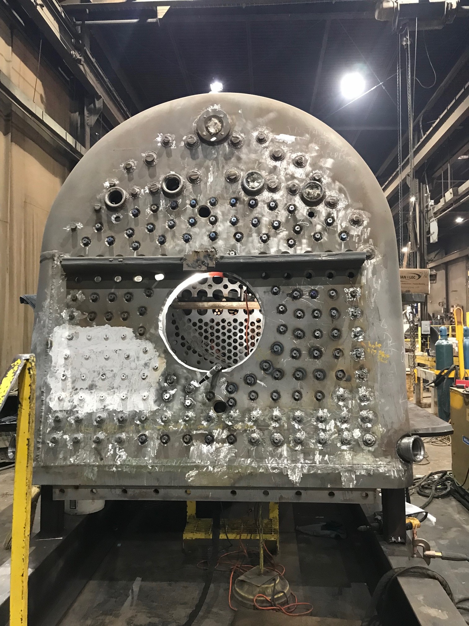
The wrapper sheet was fit to ensure all of the firebox stay locations lined up correctly then removed so that we could drill the firebox, as you can see the doorsheet is all that needs to be drilled. After this is complete the wrapper will be fit and welded for the last time and the entire boiler assembly will be welded together, followed by stay installation.
This photo shows the test fit of 1385’s wrapper sheet and progress with drilling. Photo courtesy Continental Fabricators
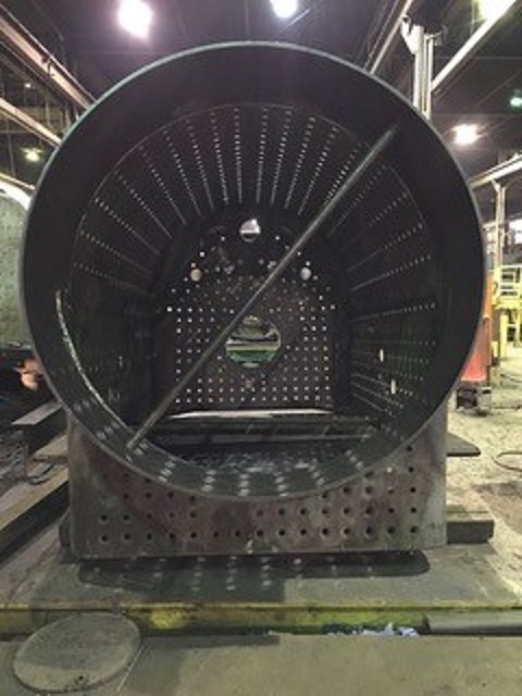
View looking down the barrel of C&NW 1385’s new boiler as of late November 2018. Photo courtesy Continental Fabricators.
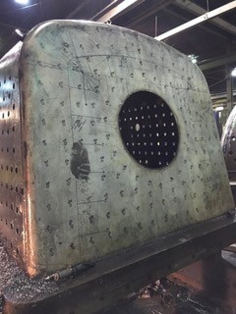
1385’s door sheet is the only part left to be drilled. Photo courtesy Continental Fabricators.
When the boiler is completed it will be delivered to Wisconsin where the locomotive will be assembled at the shop of SPEC Machine.


