Creamer's Automatic Ventilator
Monitor roofs with their
elevated
clerestory
were designed for two purposes: to
provide light and to provide ventilation. Open car windows provided a breezy
“effect” but seldom provided passenger with any real fresh air. And the
“fresh”
air they did provide was likely to be dusty and filled with smoke and cinders.
One of the first
improvements was to pivot the windows in the middle so that one end swung in
when the other swung out. When swiveled partially open so the projecting portion
was away
from the direction of travel, the air blowing past the opening created a slight
vacuum, pulling out stale air and presumably allowing fresh air to enter through
vents or a transom in the end of the car. (Same principle as the “wing” windows
in 1940-57 cars [before wrap-around windshields].)
The idea worked well enough if the brakemen positioned the
windows correctly. But he did not, and the projecting end was
into the
direction of travel, it acted as an air-scoop, bringing
in dust and
dirt, rain, snow, cold air, and the ever-present cinders and smoke. But brakemen
generally had other, more pressing duties such as tending the stoves, trimming
the lamps, reversing seats, etc. not to mention manning the brakes, and often
the clerestory windows did not get set properly.
 |
| (
Car-Builder’s
Dictionary,
1879 edition) |
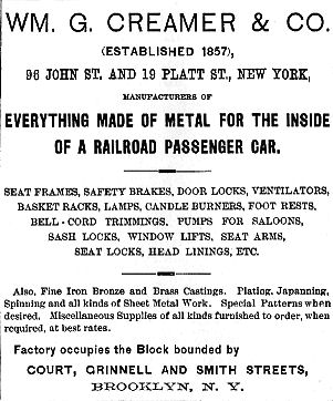
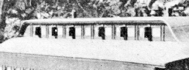
A railway supplier named William G. Creamer sought to solve
the problem with a ventilator that set itself automatically to the
direction of travel. He designed an open-ended sheet metal box that could be
fastened to the
deck side
with the openings positioned in the directions of travel (see photo above).
Inside was a “Y”-shaped flapper valve (see illustration below) that set itself
in the proper direction.
 |
Outside view of Creamer's Automatic
Ventilator. In this view, A represents the side of the ventilator against
the deck side. B is the outside of the ventilator. The car is moving to
the right, pushing the vane C to the left. The air moving past the
ventilator on the outside (from right to left) creates a slight vacuum,
pulling air out of the car through the opening D. |
|
This is a cross section of the
ventilator looking down. A is the deck side. B is the outside of the
ventilator. C is the vane being pushed from its
“normal” position E. D is the opening into the car through which air is
sucked out as in the illustration above. |
 |
 |
|
Creamer’s
Automatic Ventilators on the deck of a clerestory-roofed passenger car
about 1876. Either the deck windows have been replaced with solid panels
or simply appear opaque because of the sun's reflection. |
The ventilator wasn’t Creamer’s first or only invention.
He had also created an “emergency brake” for railway cars. See it
HERE.
For more information on passenger car ventilation and/or brakes --
White, John H.
The American Railroad Passenger Car.
Baltimore, MA: Johns
Hopkins University Press, 1978.


