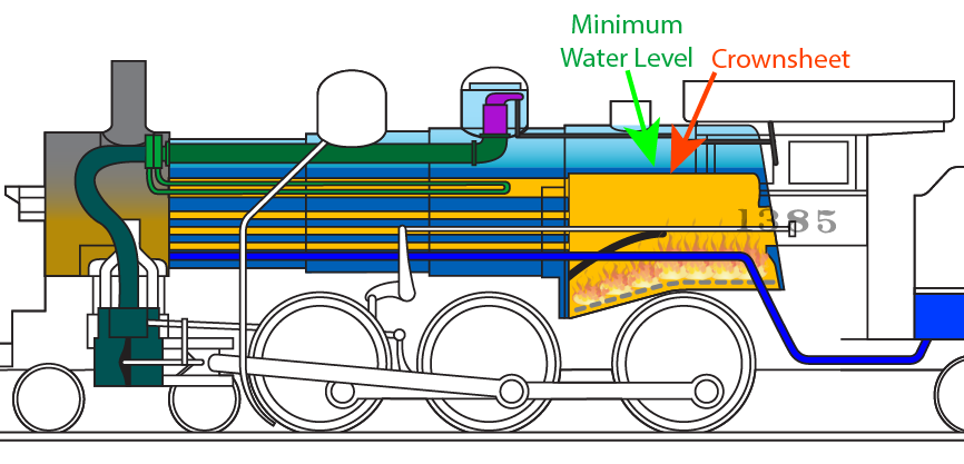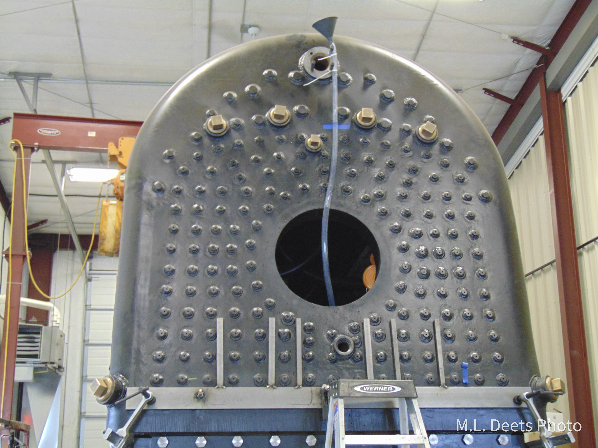
The latest accomplishment on the 1385 boiler has been the installation of the Try-Cocks. That is the proper name of an important set of monitoring and safety devices. In previous posts the question “What’s the first 3 things to know about any boiler?”, was asked and the answer is still “Where’s your water?“, times three. It was also shown the highest point of the crown sheet was measured and marked. We are additionally required to install water level indicating devices whose lowest reading shall not be less than 3 inches above the highest point of the crown sheet.
Close study of the locomotive drawings has shown (Thanks, Ed) that the C&NW standard was to install the indicating devices to show not less than 4 inches of water, giving us an extra inch of safety margin. One of the types of indicating devices is a set of three Try-Cocks, so named because they allow the operator to “Try” the level of the water in the boiler.
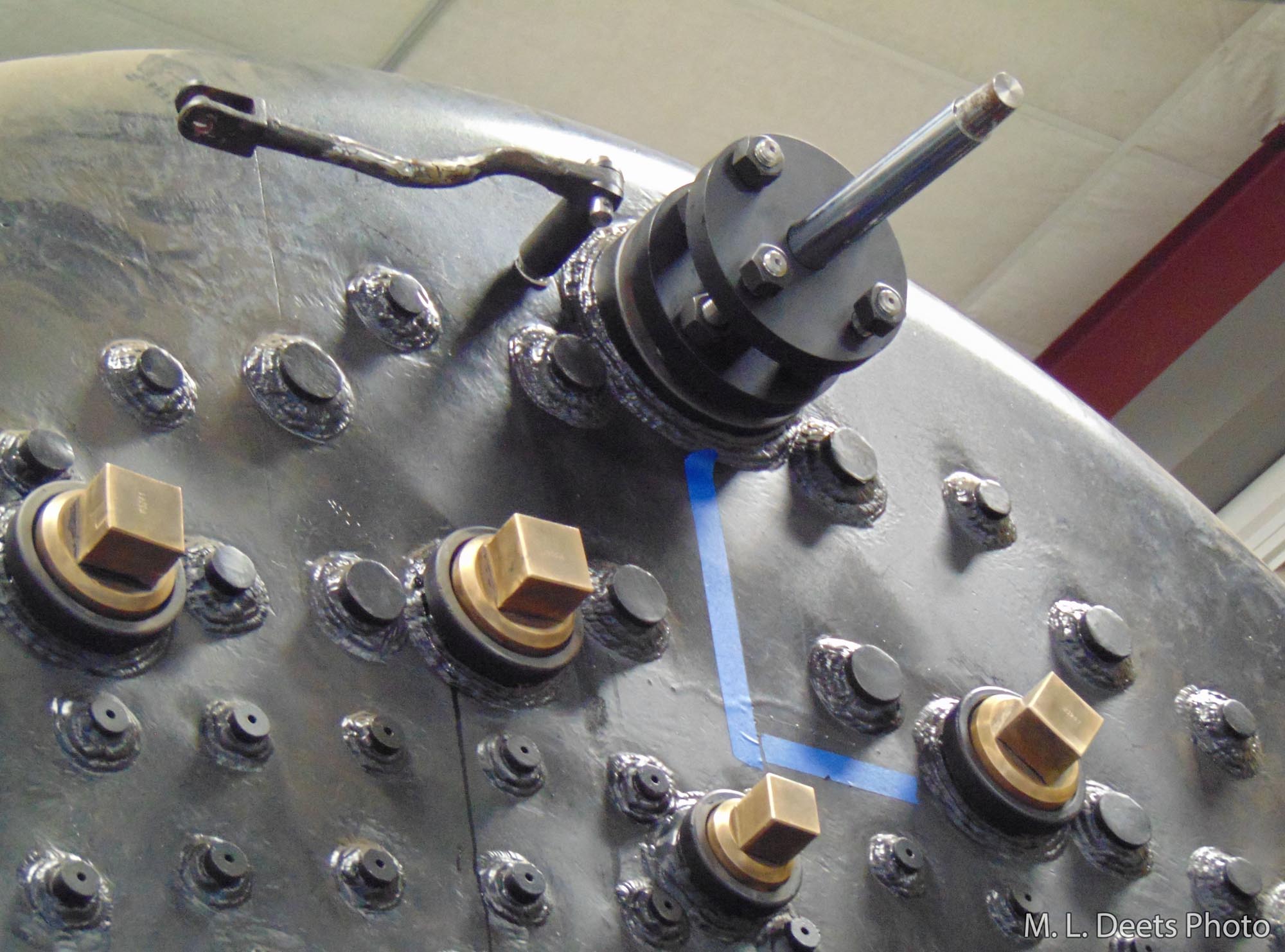
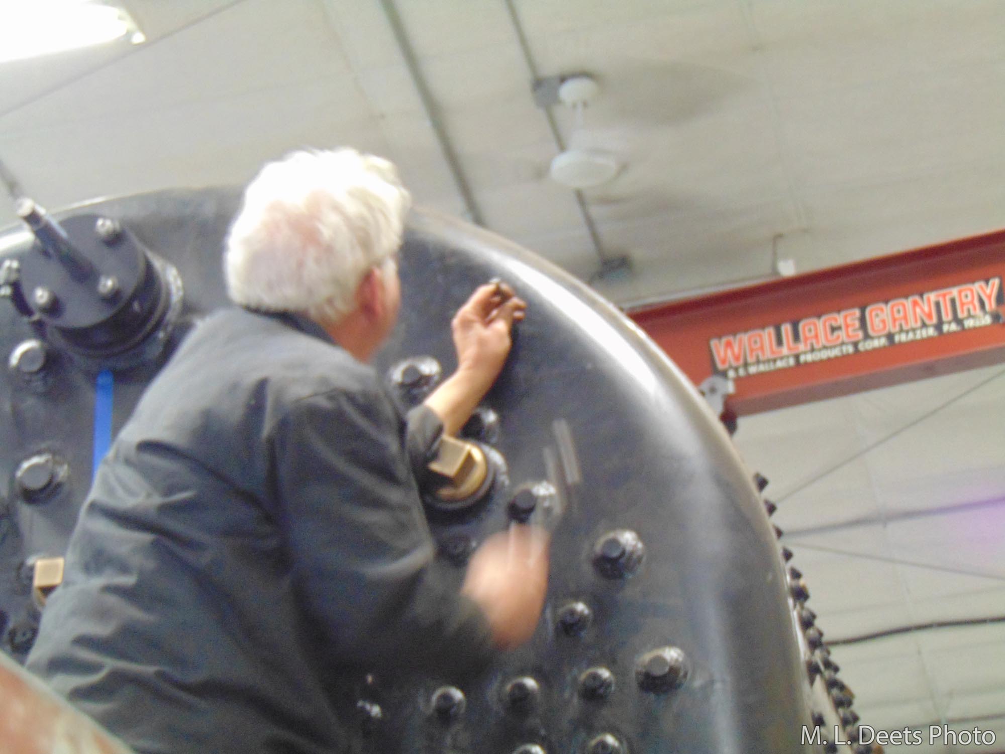
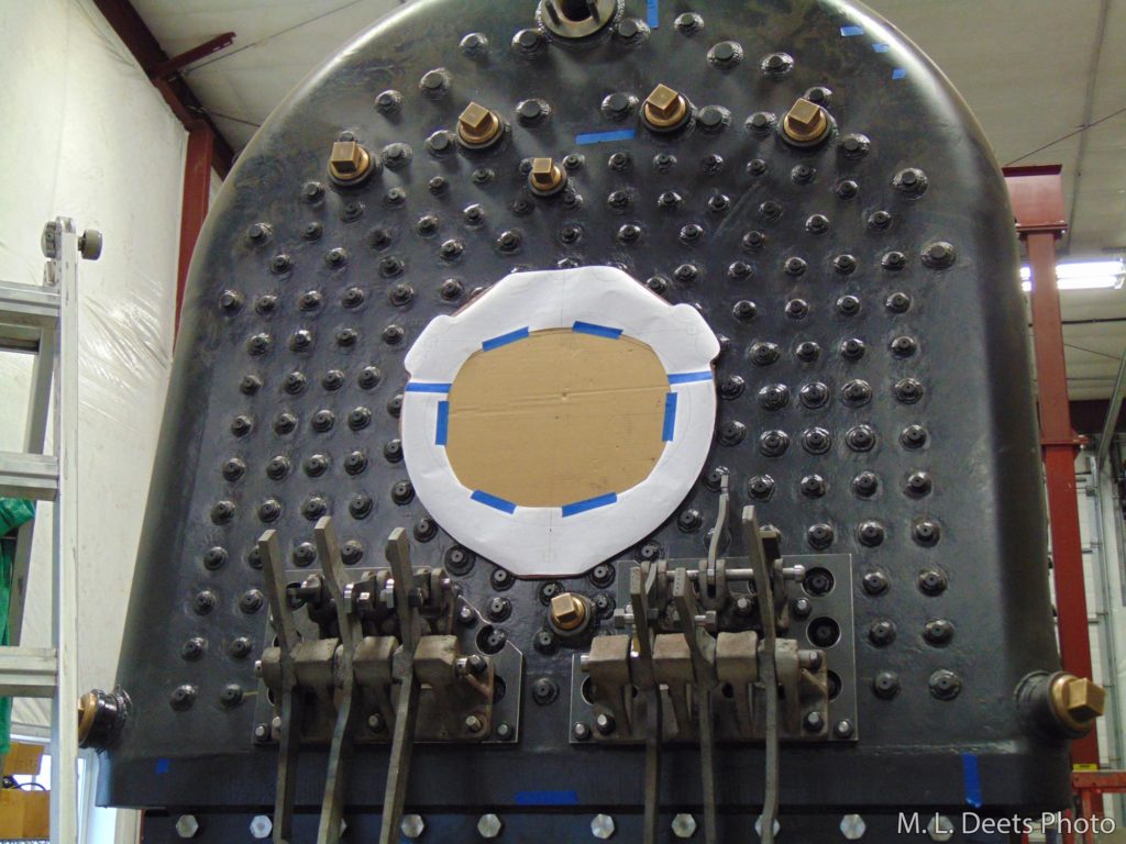
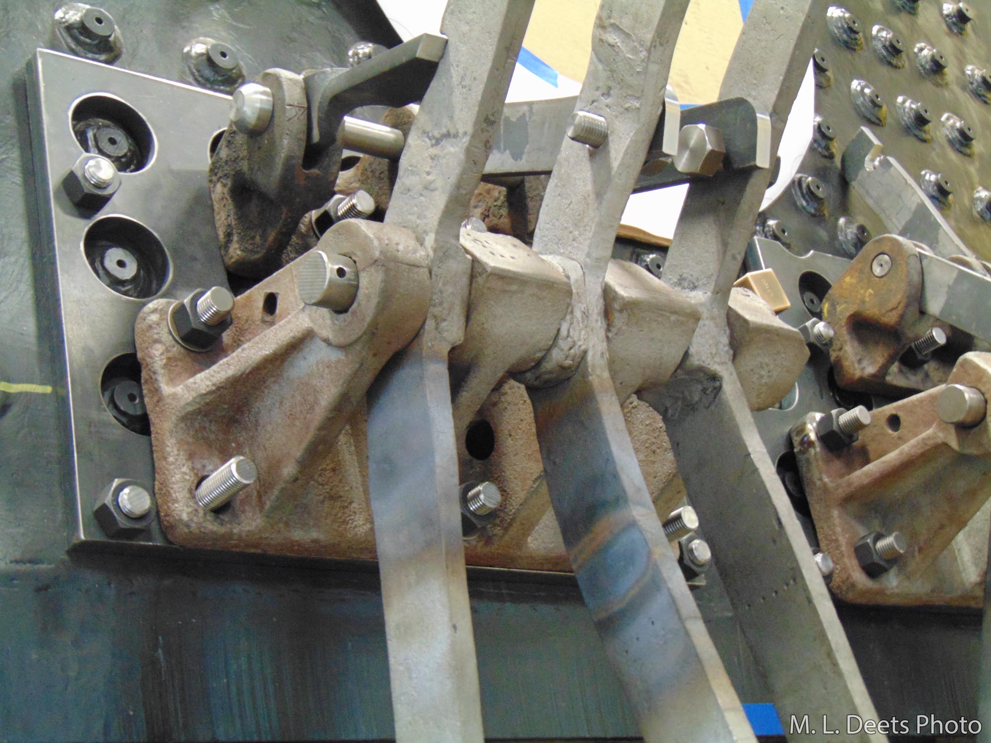
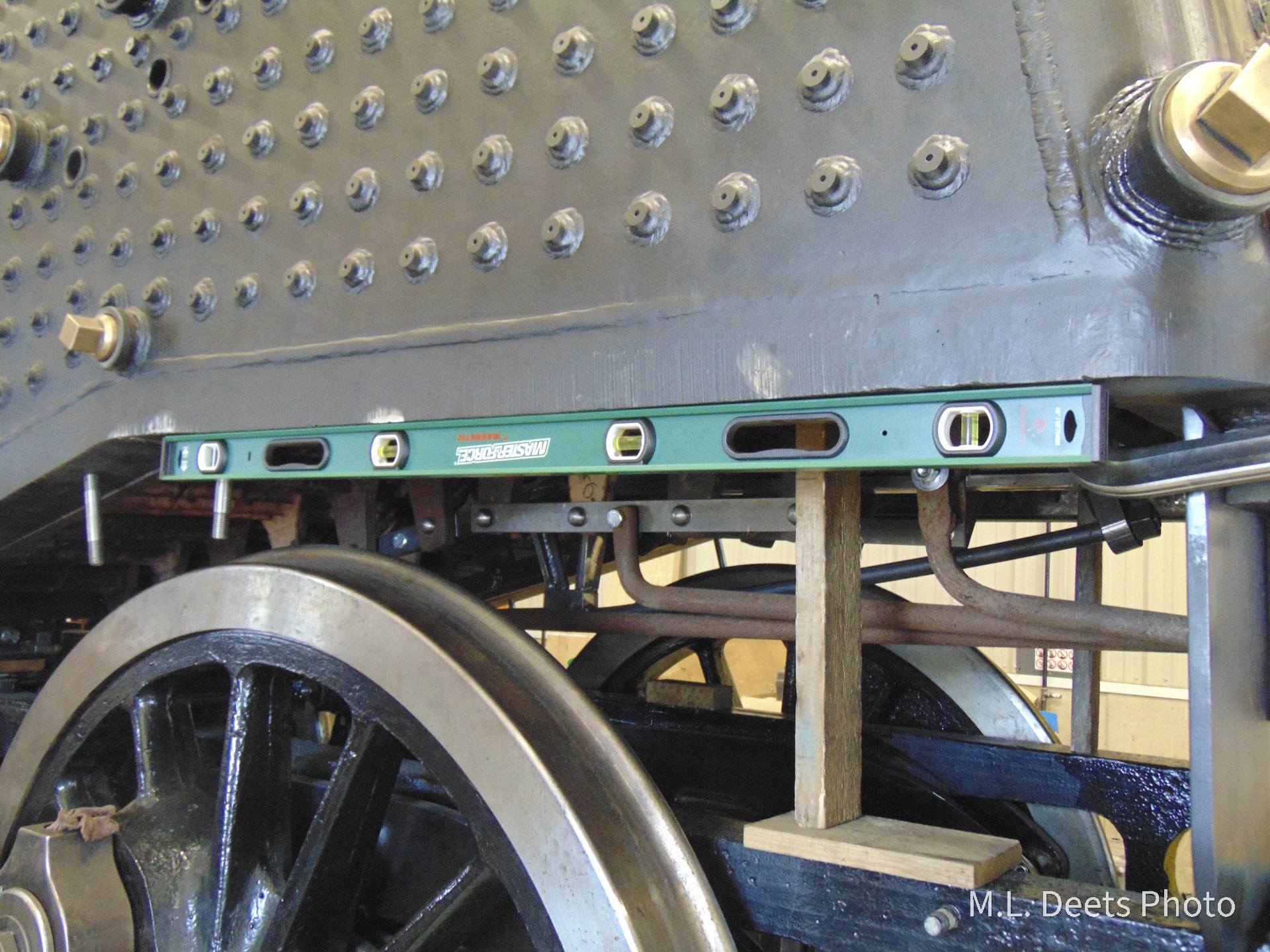
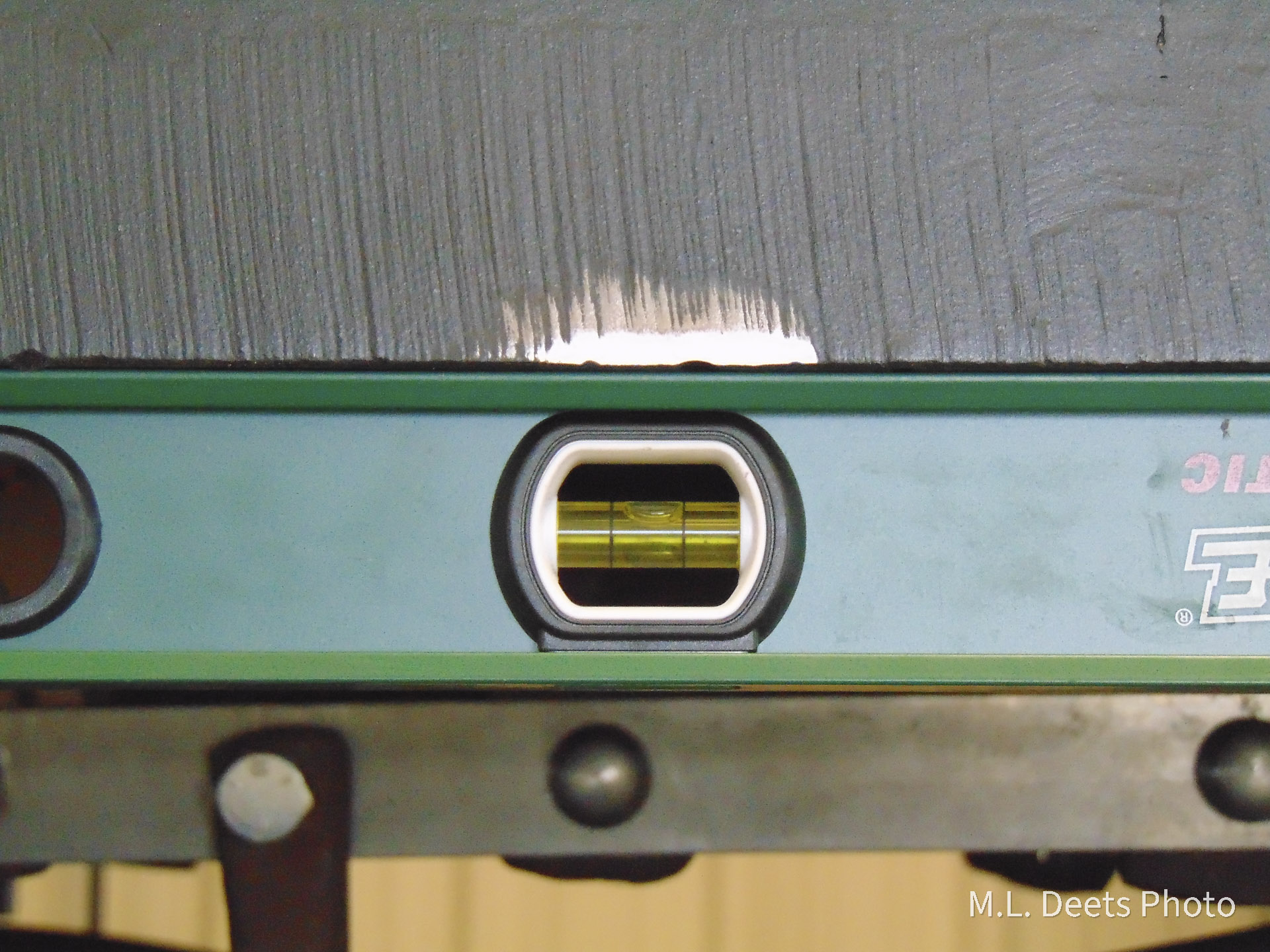
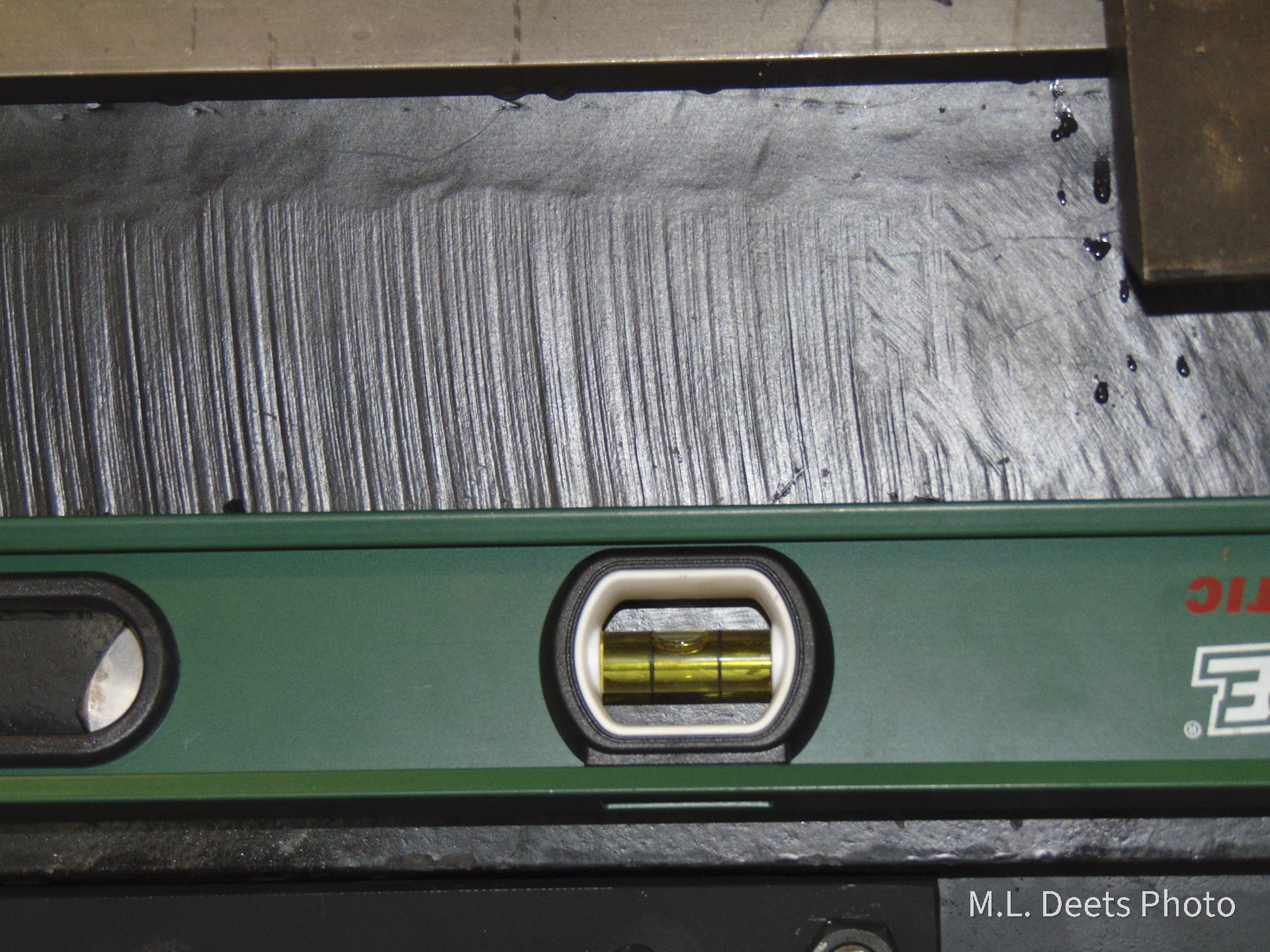
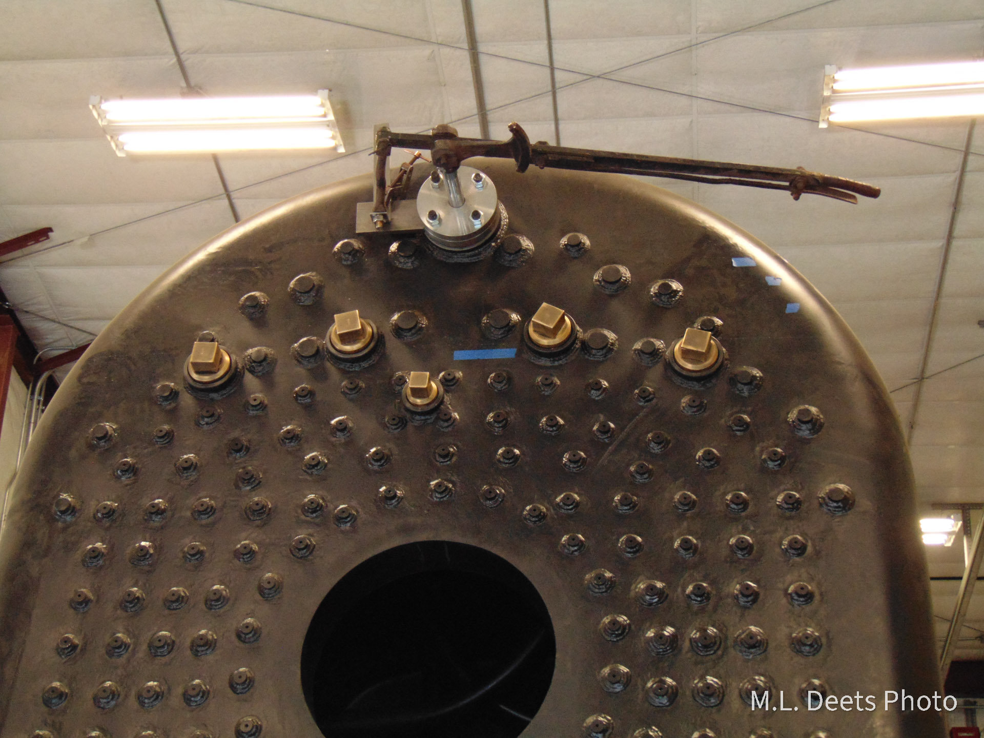
In the first picture the punch marks showing the water side of the crown sheet can be seen just above the blue tape. Steve R. of SPEC Machine works so quickly it is sometimes hard to catch a clear picture as evidenced by the photo of him placing a punch mark to locate the center of one of the Try-Cocks. A hole is then drilled and threaded to accept the base or “spud” of each Try-Cock.
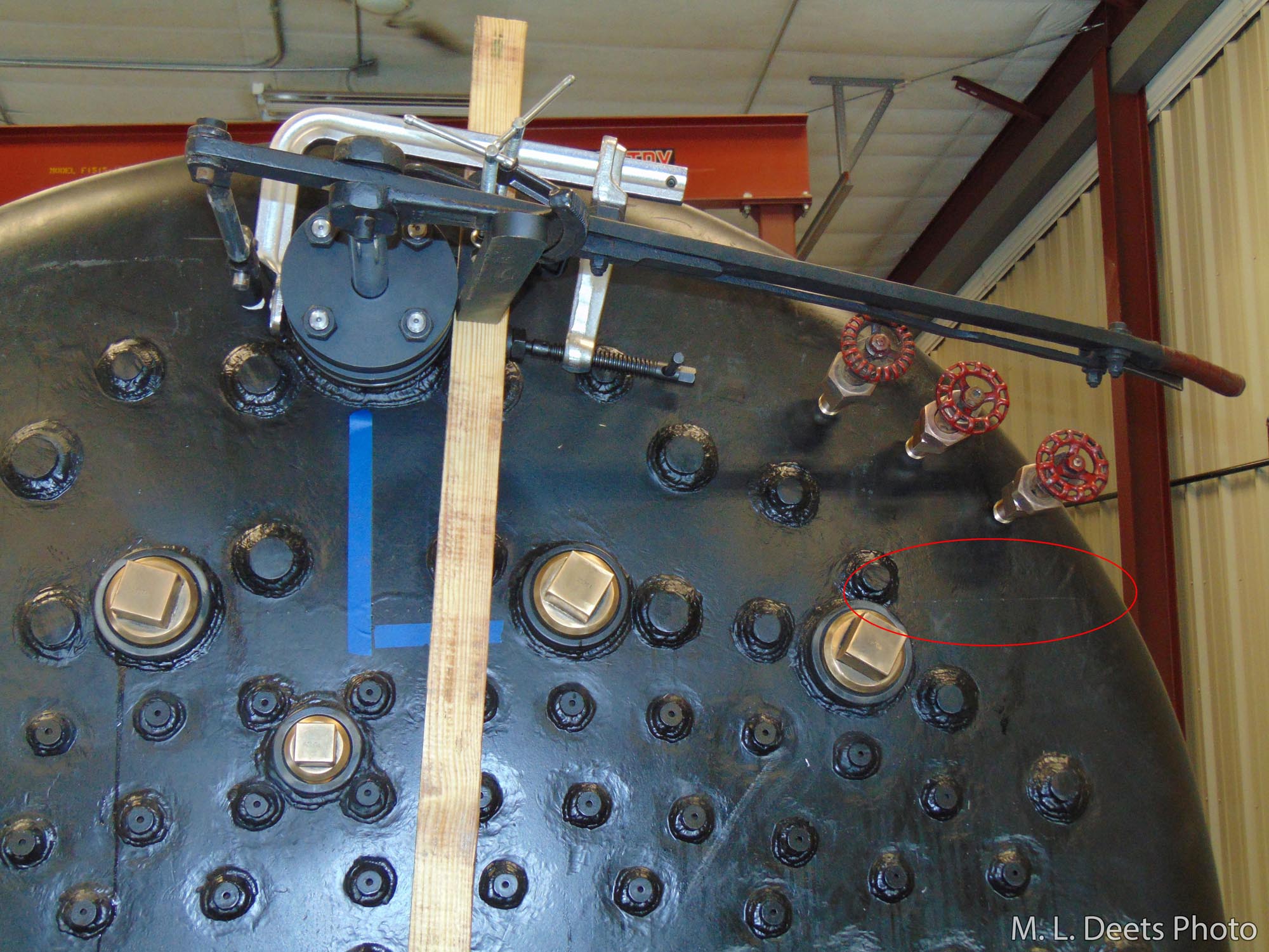
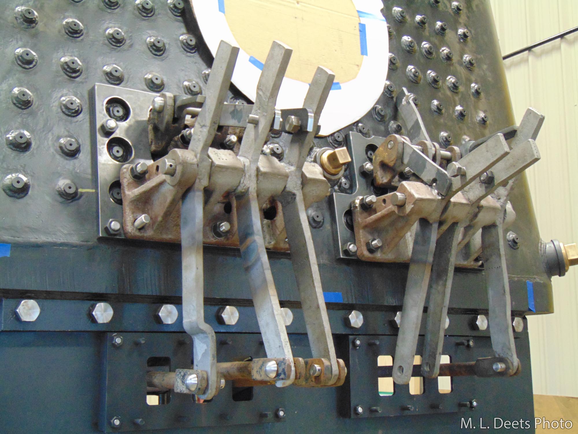
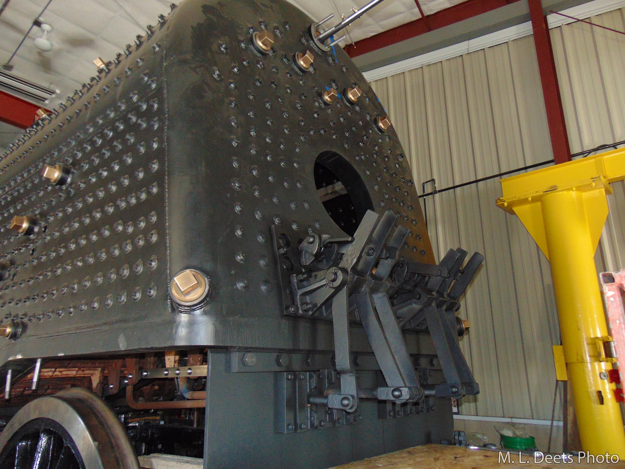
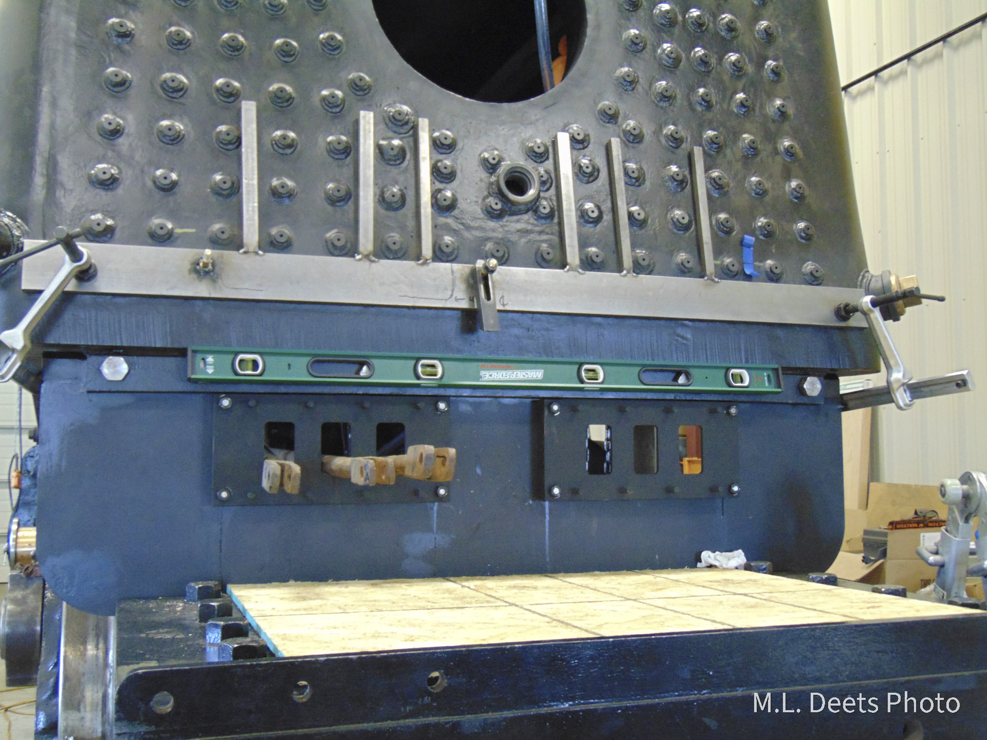
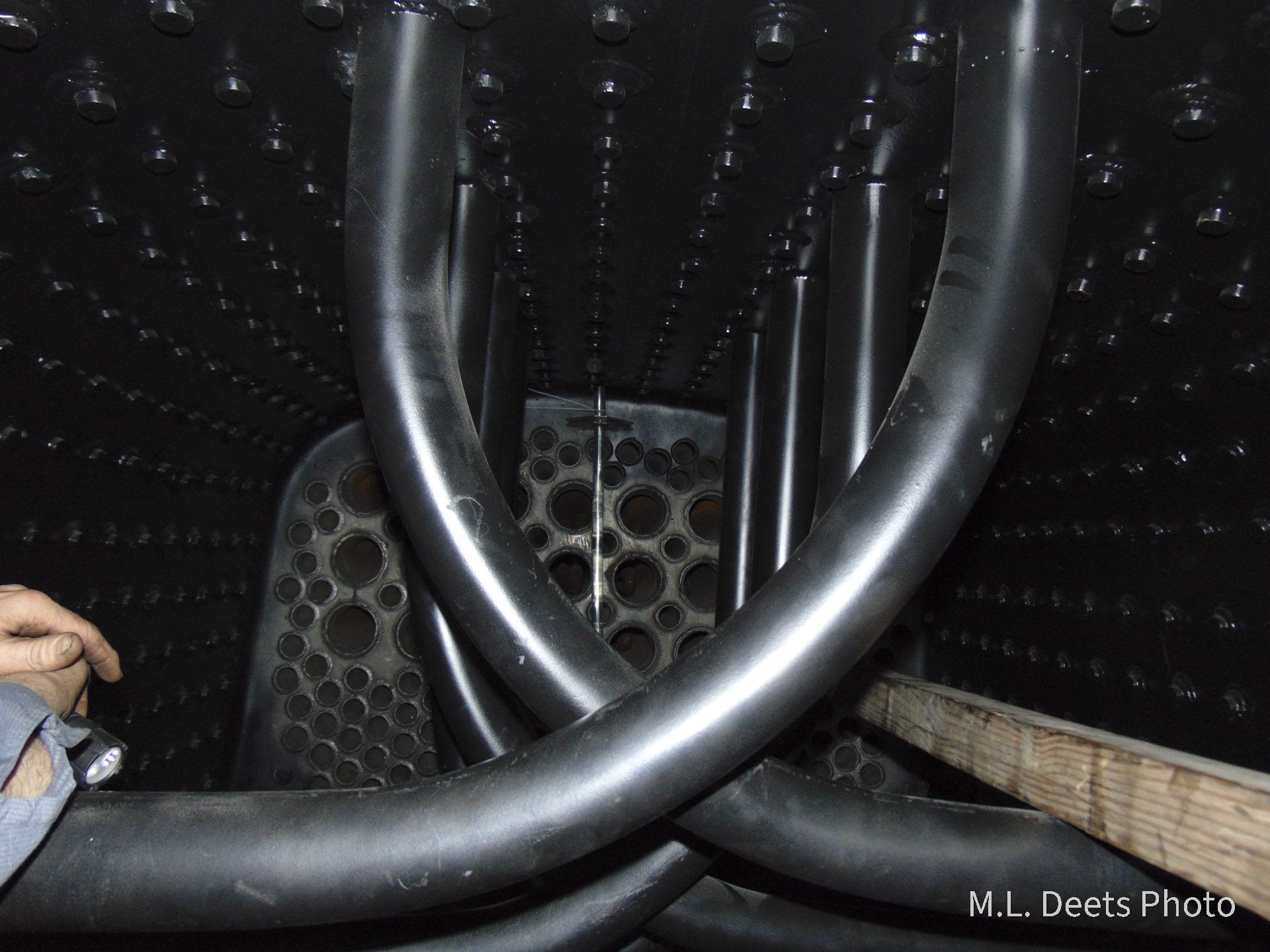
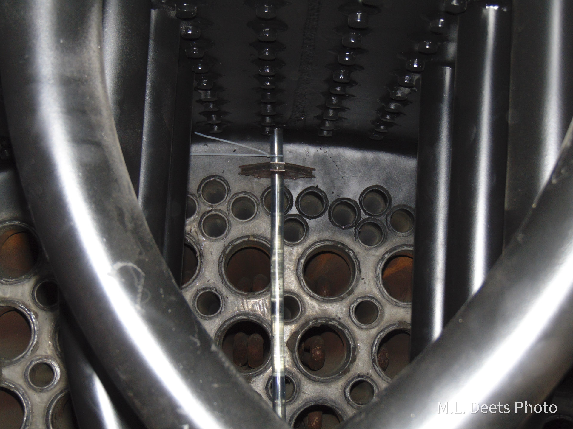
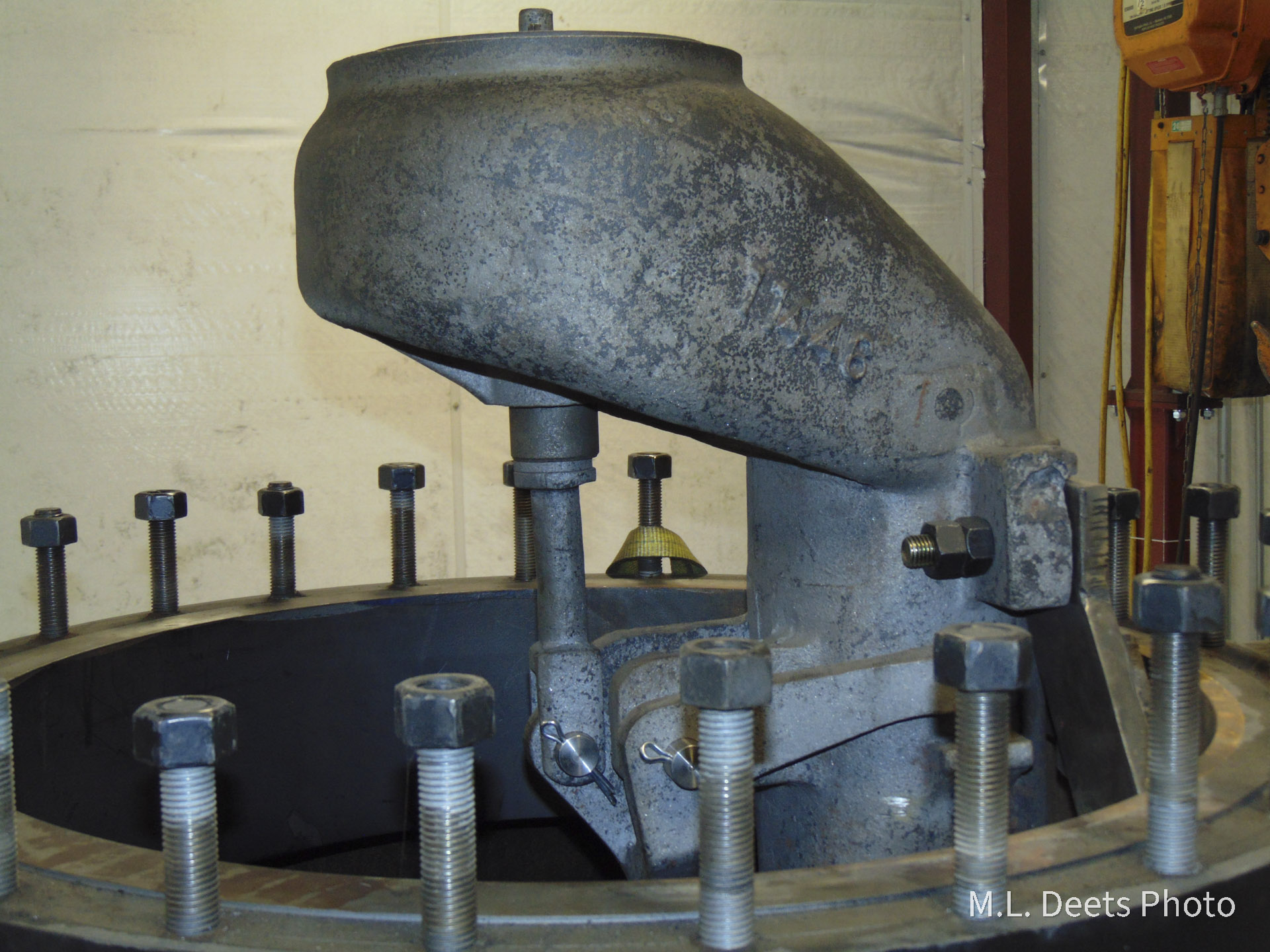
The above shot shows all three in place along with a temporary placing of the throttle handle to check clearances. This is part of the 3-D chess necessary to make sure all the components will fit before they are installed. In the circle is a marking of the water side of the crown sheet so we can be sure the lowest Try-Cock is at the proper level.
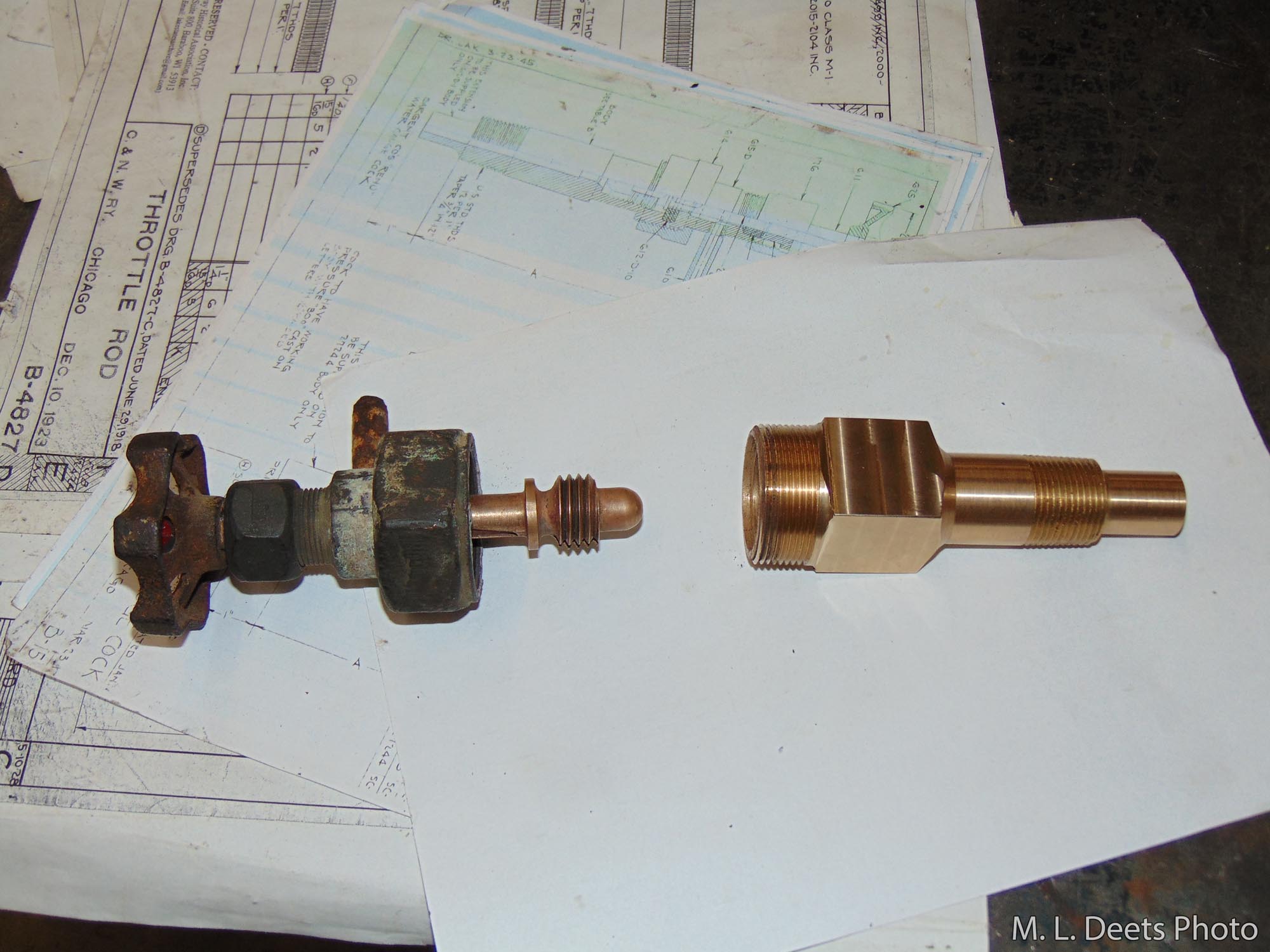
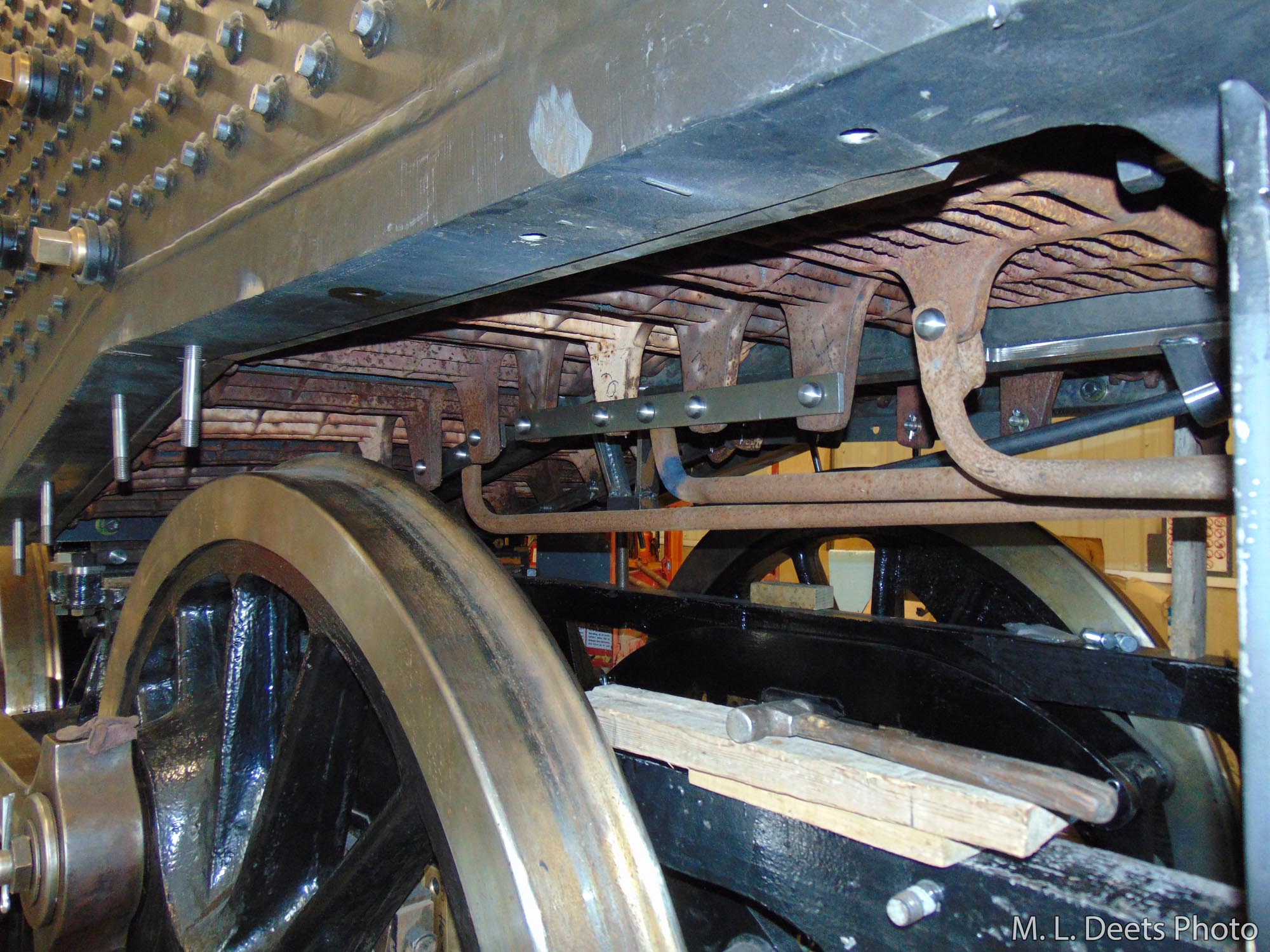
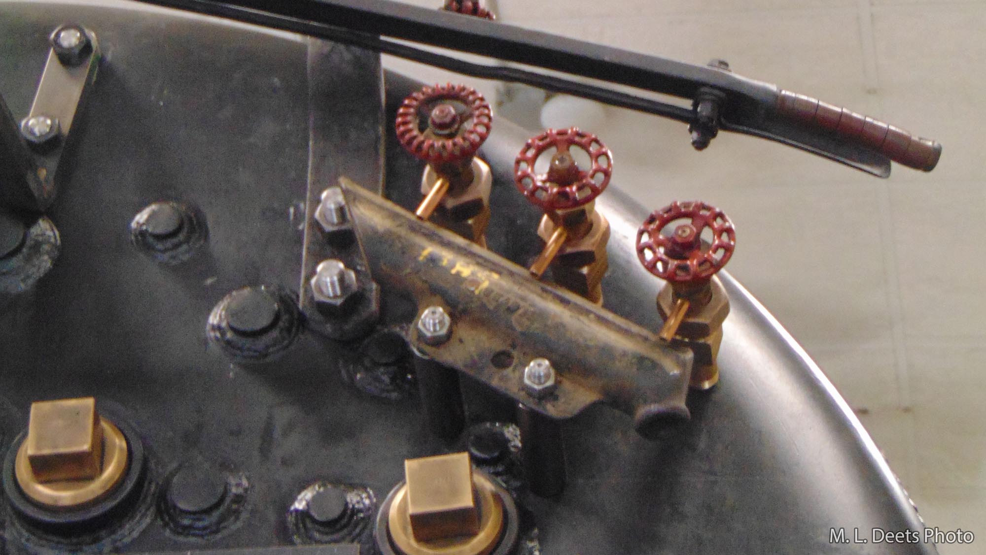
The Try-Cocks themselves are a mixture of new and old. As seen here, the bonnets and stems are original to the 1385 but the spuds were machined from a new piece of code-compliant material. This was necessary because the new boiler has a reinforcing plate applied to the inside of the backhead in order to meet with the strength requirements of the current construction code. This means the steel in that area is much thicker than the original boiler and in order to properly reach far enough into the water space the spuds needed to be longer.
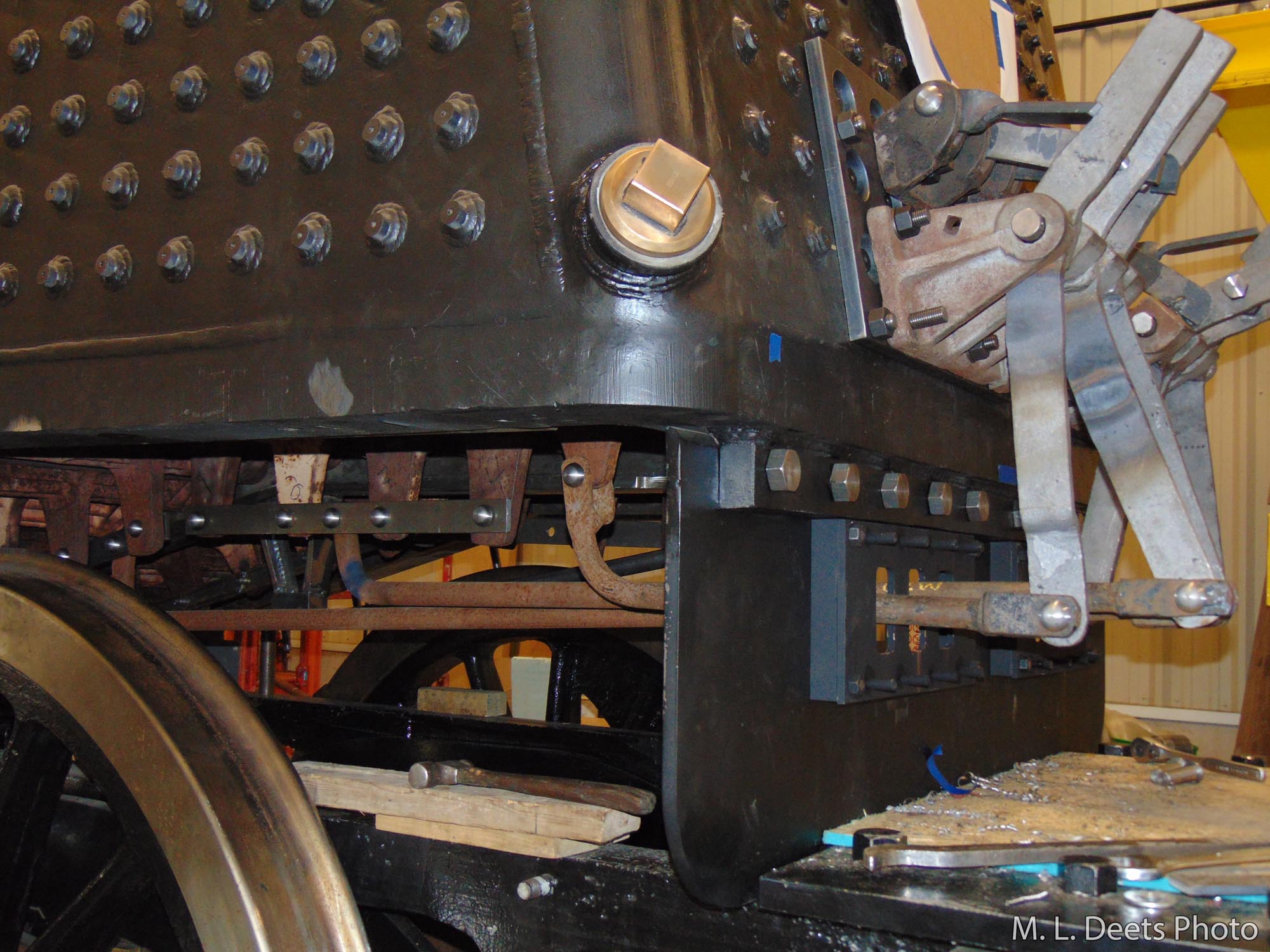
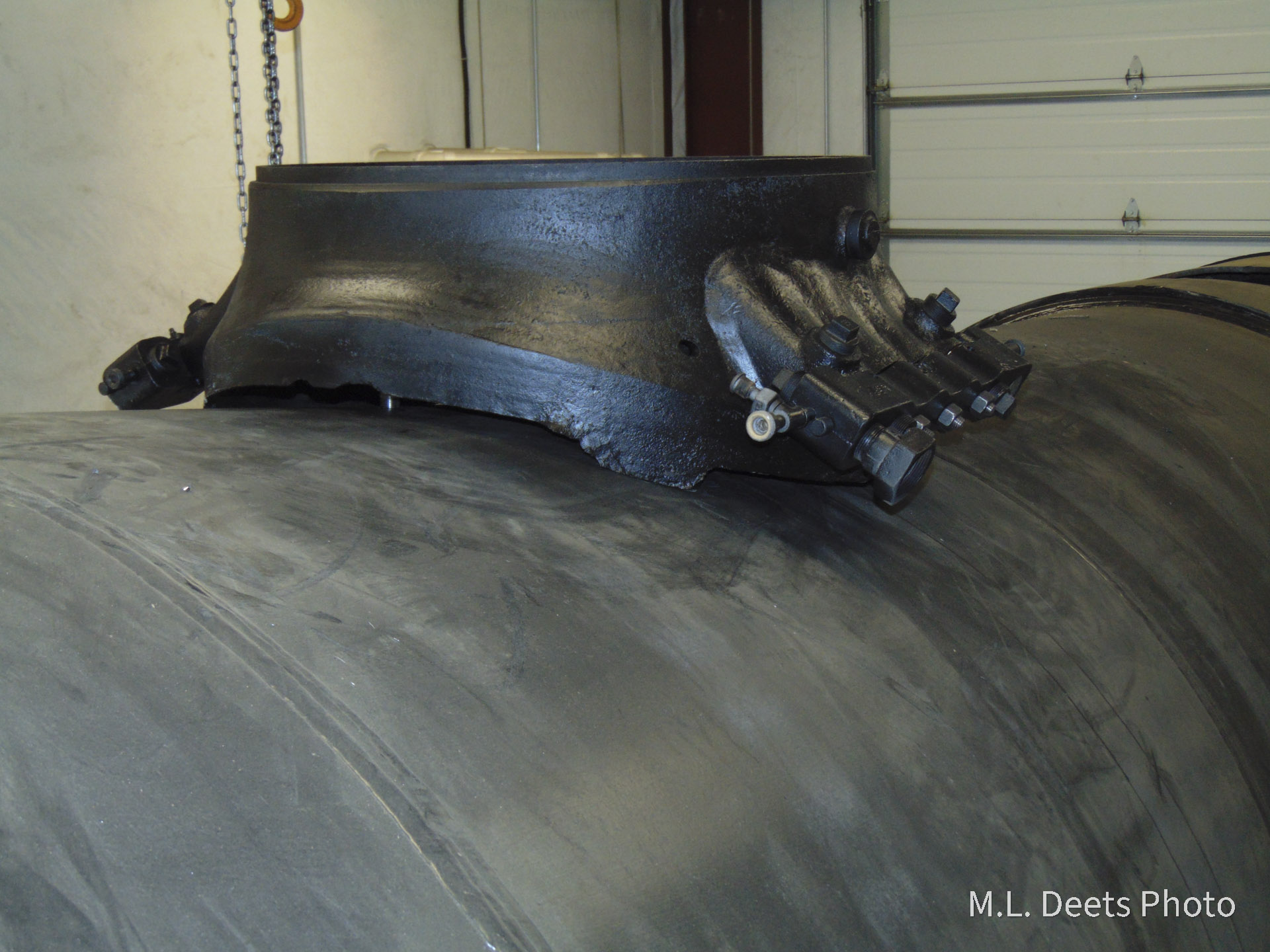
Each Try-Cock has a drain tube installed in the valve stem to direct the steam and water into the drain cup when the valve is operated to “Try” the water level. Below is how they look after final installation of the spuds, stems and drain cup. The drain cup will have a pipe that extends through the cab floor to drain the water out onto the right-of-way.
In Upcoming Updates: The throttle handle and rod as well as the engine lubricator.