Driving Wheel Overhaul Underway at Strasburg
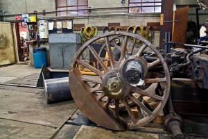
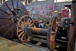
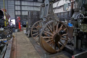
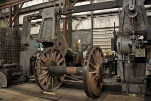
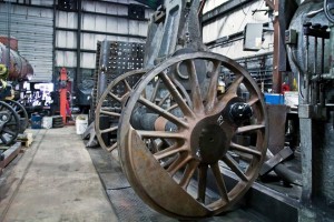
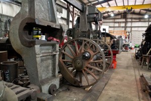
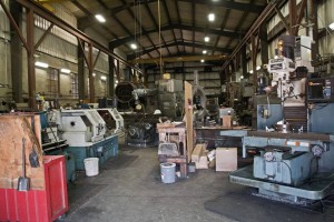
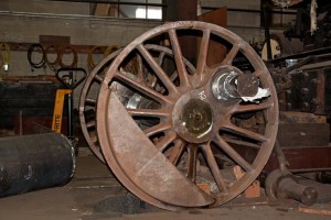
On March 30, 2014, C&NW 1385’s three sets of 63-inch driving wheels were shipped from Wisconsin to the Strasburg Rail Road in Pennsylvania in order to be “turned” on a lathe, receive new tires, and have other adjustments and repairs completed (scroll down to the March 30th post for additional detail). On the weekend of June 28, 2014, Mr. Bernard Krebs of Jim Thorpe, PA photographed the drivers for the benefit of this steam status page, allowing us a glimpse of the work in progress.
- C&NW #1385 driving wheels at Strasburg Railroad. June 28, 2014. Bernard Krebs photo.
- C&NW #1385 driving wheels at Strasburg Railroad. June 28, 2014. Bernard Krebs photo.
- C&NW #1385 driving wheels at Strasburg Railroad. June 28, 2014. Bernard Krebs photo.
- C&NW #1385 driving wheels at Strasburg Railroad. June 28, 2014. Bernard Krebs photo.
- C&NW #1385 driving wheels at Strasburg Railroad. June 28, 2014. Bernard Krebs photo.
- C&NW #1385 driving wheels at Strasburg Railroad. June 28, 2014. Bernard Krebs photo.
- C&NW #1385 driving wheels at Strasburg Railroad. June 28, 2014. Bernard Krebs photo.
- C&NW #1385 driving wheels at Strasburg Railroad. June 28, 2014. Bernard Krebs photo.
Strasburg Rail Road makes use of a 90-inch Niles wheel lathe originally sold to the Lehigh Coal and Navigation Company in 1912. Lathes of such sizes were commonplace in the major railroad shops of America when enormous steam engines commonly roamed the rails, but now are rare with a limited number of shops around the country capable of handling tasks of such size.
Modern railroad equipment still undergoes similar maintenance procedures but all feature smaller wheels. The electric traction motors used on modern locomotives make wheel size relatively unimportant compared to steam locomotives where wheel diameter directly impacted piston speeds.
During each full rotation of a driving wheel on a steam locomotive the piston and connecting rods change direction of motion twice (forward then back). This very rapid change of direction puts a large amount of stress on the parts involved. Therefore, increasing the distanced traveled per wheel revolution and thus reducing the number of back-and-forth piston motions per second was an important design feature for high speed operations. It is no coincidence that the Milwaukee Road Class A and Class F7‘s that were built for 100 MPH-plus running of the Hiawatha trains between Chicago, through nearby Wisconsin Dells, and on to the Twin Cities featured massive 84-inch driving wheels. The British LNWR 2-2-2 3020 Cornwall is an extreme example of this concept, featuring 96-inch driving wheels.
Per Wikipedia, “Freight locomotives generally had driving wheels between 40 and 60 inches in diameter; dual-purpose locomotives generally between 60 and 70 inches, and passenger locomotives between 70 and 100 inches or so.” Compare C&NW 1385’s drivers with those of Saginaw Timber Company No. 2 as an example. In order to attain a speed of 60 MPH, No. 2’s 44-inch drivers would require roughly 7.6 revolutions per second while No. 1385, built for fast freight and secondary passenger service, features 63-inch drivers that would require roughly 5.3 revolutions per second. Worded differently, it means the 1385 can travel 30% farther using the same number of piston motions. The Class A or Class F7’s 84-inch drivers meanwhile would only require a comparatively leisurely 4 revolutions per second.

