1385 Update – Mounting Progress
As mentioned in our last update, almost every item that must be mounted to the boiler of our engine requires at least one more hole to be drilled into the boiler shell. In recent weeks the layout of where to drill some of those holes has been moving quickly. Among those completed are the holes for mounting the bell and the steps used to access and fill the sand dome. Item locations laid out and awaiting attention include brackets for the Brake Control stand, Reverser, Steam Gauge, Safety Valve and Cab turrets, and the Power Reverse Cylinder.
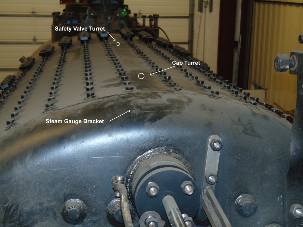
Starting at the top of the boiler, the rectangle at the near edge is where the Steam Gauge bracket will be mounted, and further back will be the Cab and then the Safety Valve turrets.
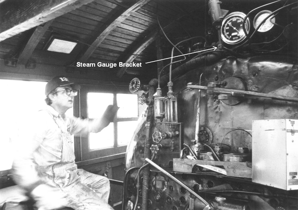
From Paul Swanson’s collection, here is the Steam Gauge location.
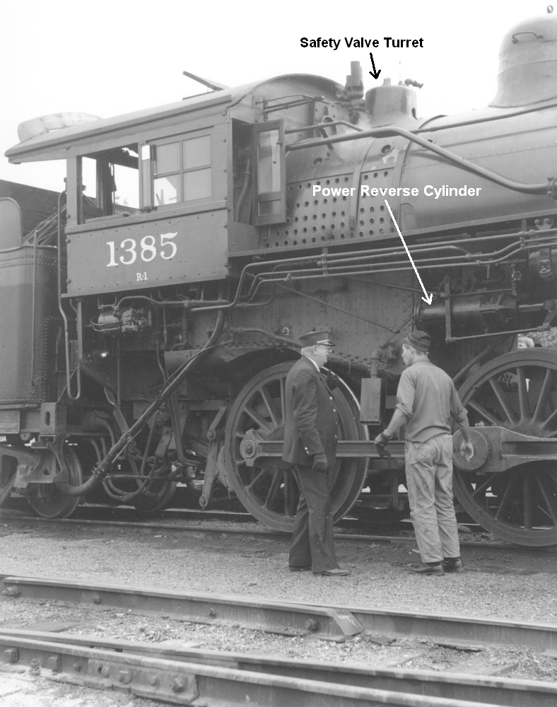
The Cab Turret is hidden behind the gauge, but the Safety Valve Turret can be seen in this shot, along with the Power Reverse Cylinder. The Power Reverse system uses an air-powered cylinder controlled by a lever in the cab to actually move the valve gear of the engine and control both the direction the engine moves and how much power is applied to the rails.
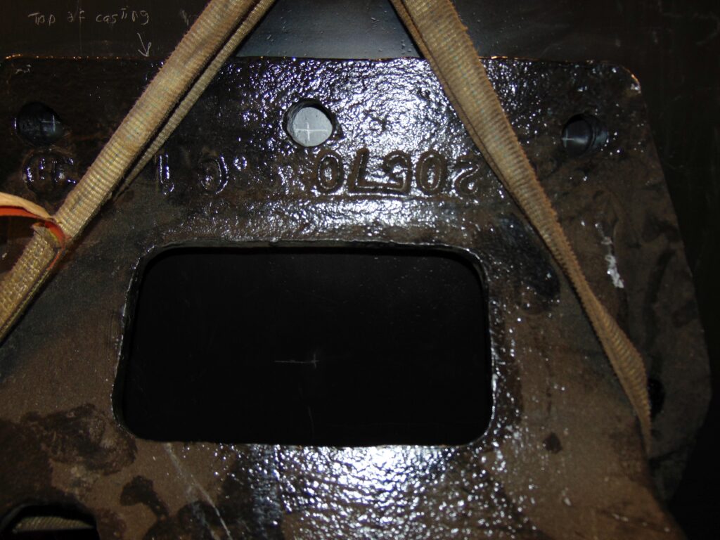
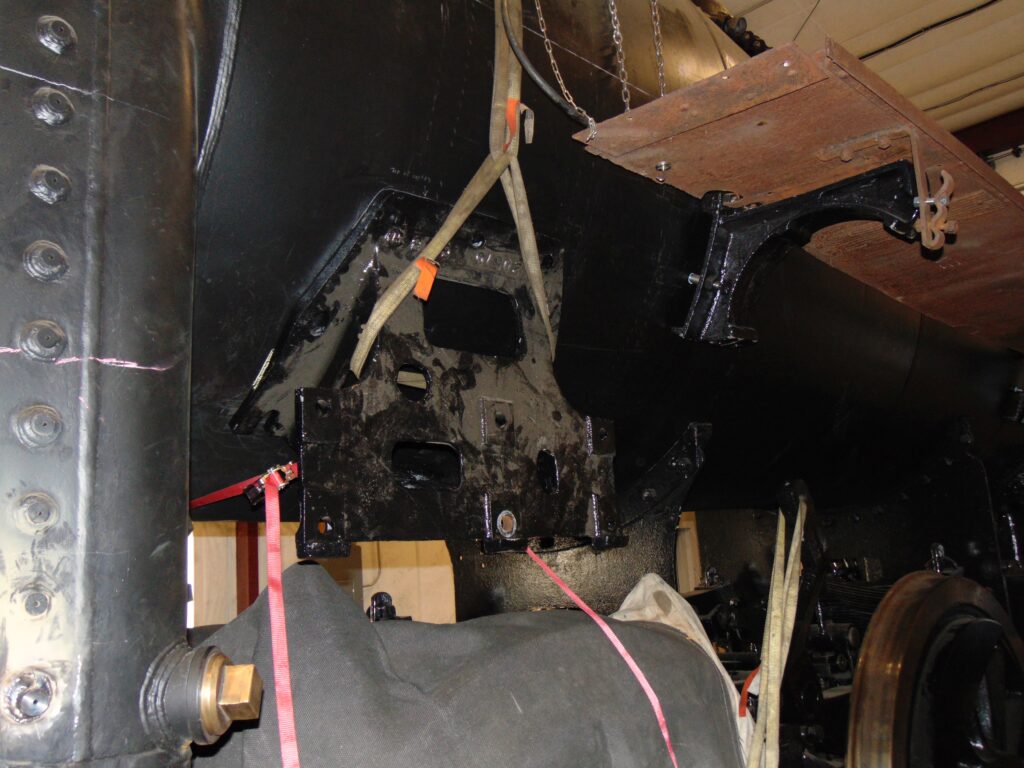
The cylinder is mounted outside the cab to this bracket and the bracket is held to the boiler shell by 7 studs. The locations for the holes were laid out using dimensions from the C&NW drawings we have, but then the bracket is strapped to the boiler so the actual locations can be transferred from the bracket itself. In several places we’ve found manufacturing differences between the drawings and the actual parts which makes double and triple checking necessary.
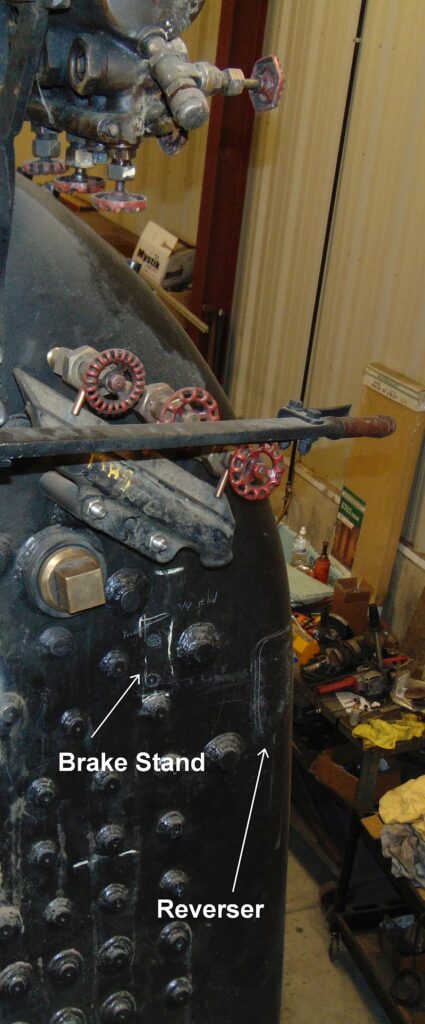
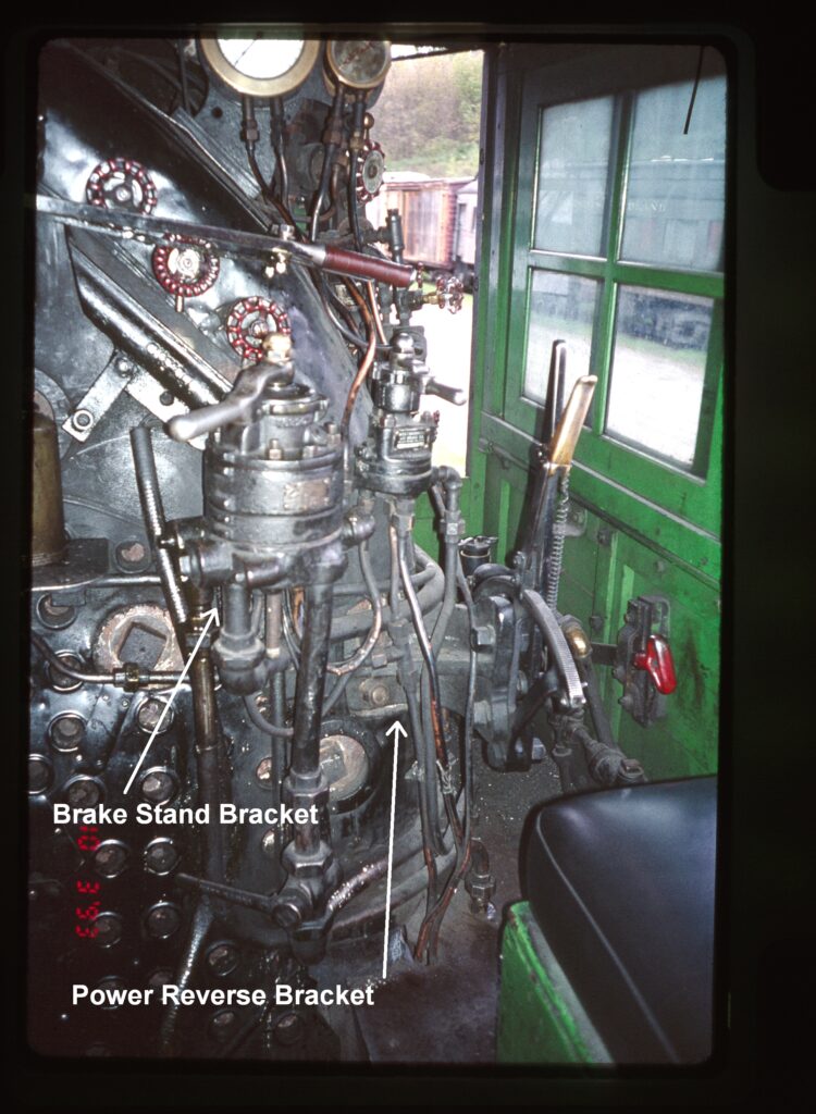
Inside the cab once again, we see the locations for the Air Brake Stand and the Reverser Lever as well as a photo from 1993 showing the actual items. The process of 3-D chess continues as we move ever closer to the FRA-mandated boiler tests.
