1385 Update: Branch Pipe Donuts and Grate Bearers
Branch Pipes Follow-Up
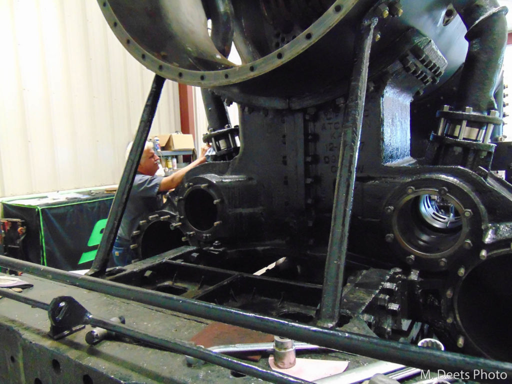
In our January 2021 Update, it was discussed that one of the upcoming tasks was to create “donuts” to insert between the branch pipe and steam chest and between the branch pipe and superheater header. That task has now been completed.
These spacer donuts are needed to adjust for minor manufacturing size differences and space variations between the new and old components. The donuts needed to each be custom made to be steam tight and to properly position on both ends of the branch pipes.
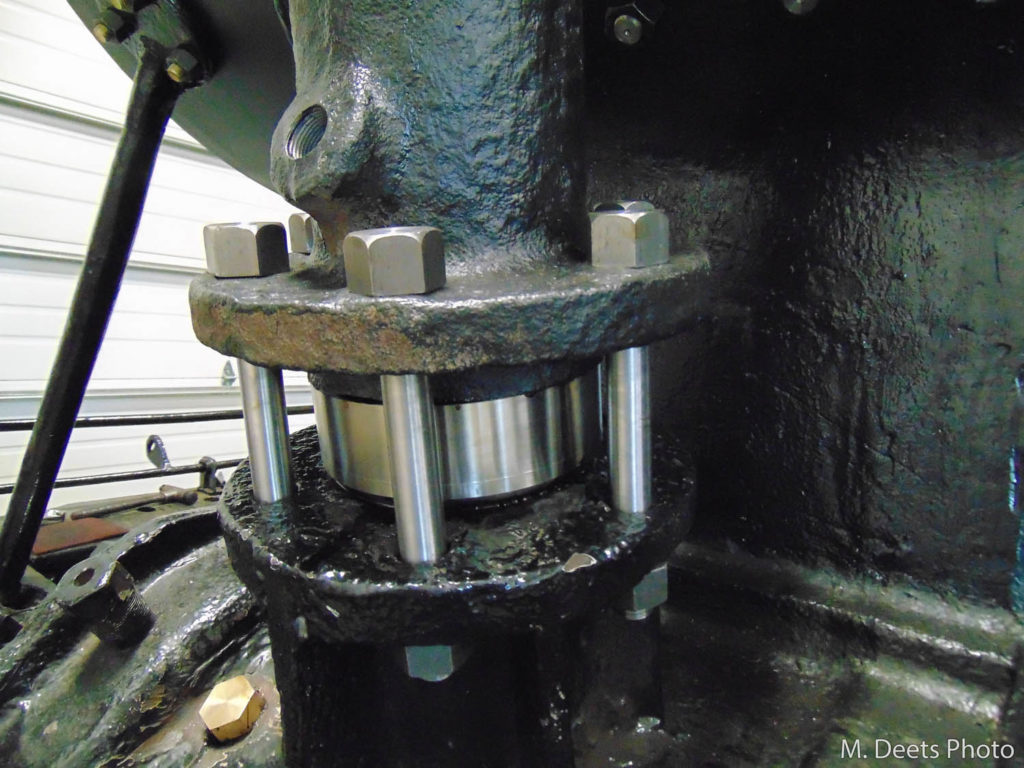
Detail view of lower end of 1385’s fireman-side branch pipe with “donut” extender. 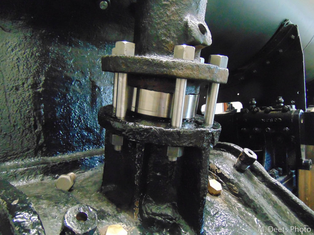
Another detail view of the lower end of 1385’s fireman-side branch pipe with “donut” extender. 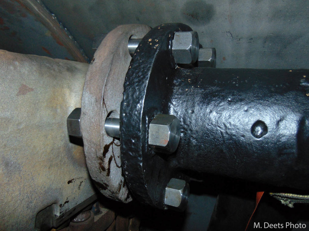
Top of C&NW #1385 branch pipe (black) on fireman side. A “donut” is being created to permit a steam-tight seal between the branch pipe and superheater header. 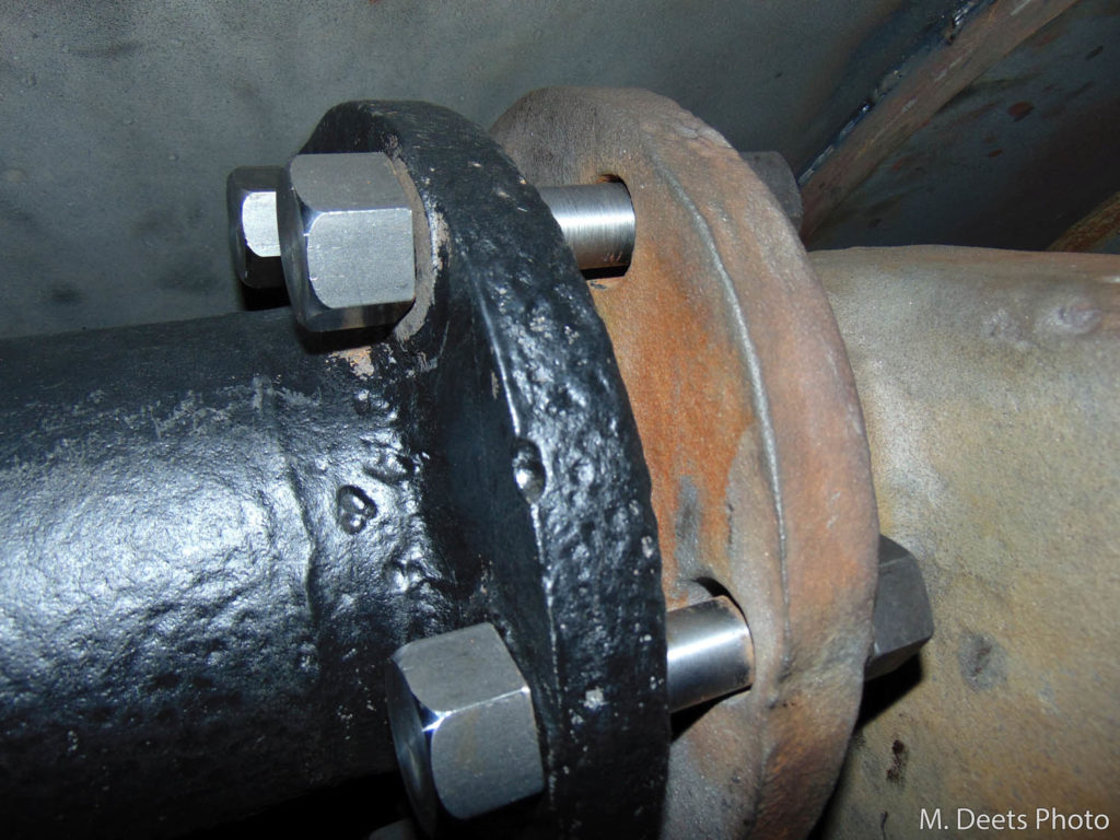
Top of C&NW #1385 branch pipe (black) on engineer side. This side will also be receiving a “donut” to close the gap to create a steam-tight seal between the branch pipe and superheater header.
Reconstructing the Grate Bearers
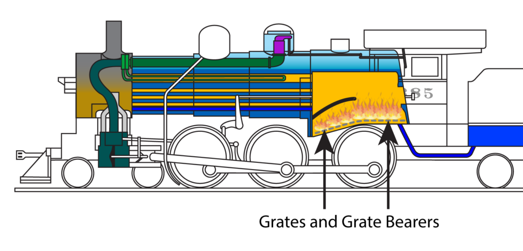
If you have a home fireplace, you know that you don’t place logs directly onto the floor of the fireplace when burning. For better combustion, the logs are usually placed on a metal grate which props the logs up and allows air to more easily flow underneath the logs and helps feed the fire with more oxygen, allowing it to burn hotter. This same concept applies when firing a steam locomotive – the grates on a locomotive are just larger and more complex, allowing the fire to be manipulated by the locomotive’s fireman.
The grates are rectangular cast iron pieces with many holes through them that form the floor of the firebox. That cast iron floor holds the coal as it burns so the locomotive can generate the heat needed to boil the water for steam.
As you look in from the firedoor there are two rows of grates that run from the front of the firebox to the back. Each row of grates is about half the width of the firebox so the dividing line (front to back) is the centerline of the firebox
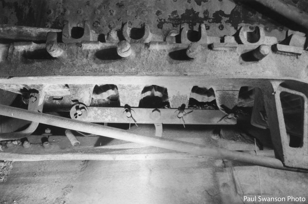
The grates are set on – and held in place by – the grate bearers. The grate bearers were originally cast iron brackets with a row of pegs to hold the end of each grate. There is a row of pegs that runs down each side of the firebox, front-to-back, and then in the center there is a bridge that runs front-to-back with pegs on each side to hold the inside end of both rows of grates.
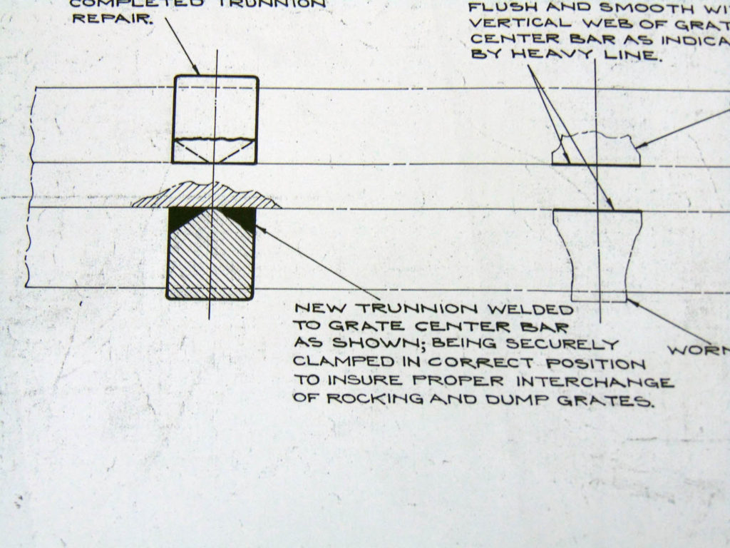
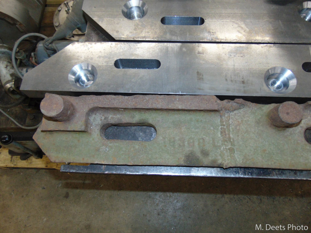
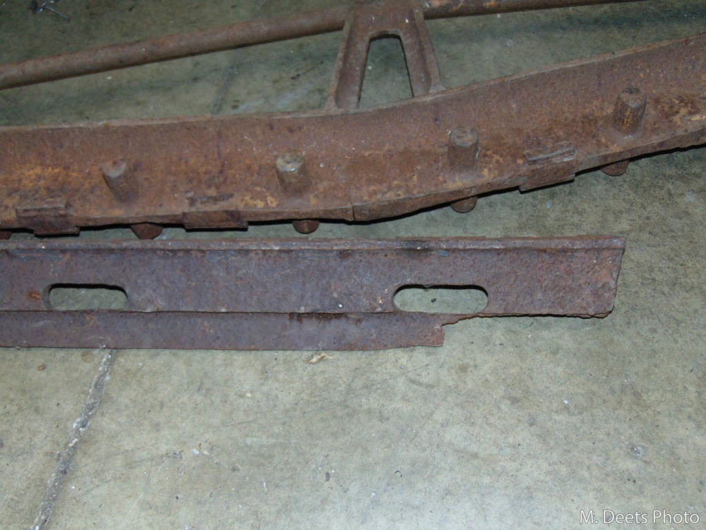
In the mid-1920s the grates were somewhat redesigned and in the later 1920s the Chicago & North Western’s repair procedures documented on the drawings said to weld the new pieces in place. During this locomotive rebuild, Mid-Continent is doing the C&NW one better and is making the new bearers an all-welded assembly. As can be seen in the photos the old bearers have been eaten away by the very corrosive nature of the ash and repaired by weld.
In these photos, the web portion of the new side bearers have been machined and are ready to accept the pegs that will be welded in place to hold the grates and lay beside the originals they will replace.
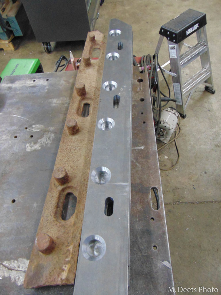
Comparison of one of the old and mostly-complete new lower side grate bearers. 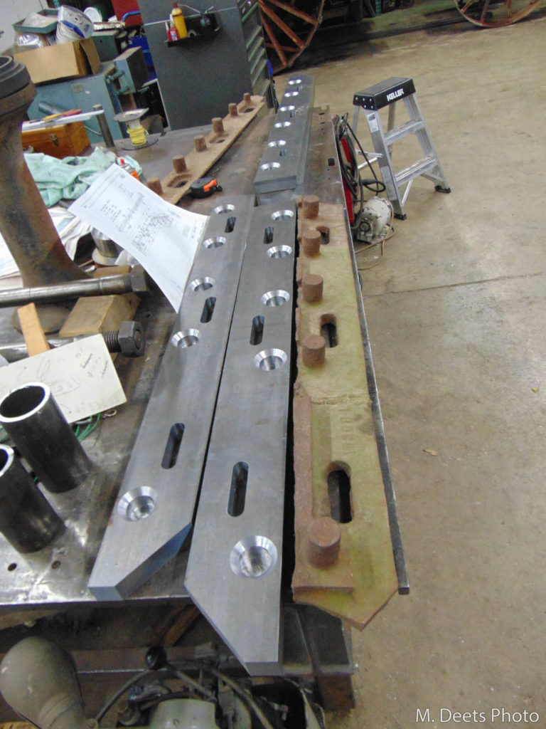
Another view comparing the two mostly-complete new grate side bars versus the old side bar. 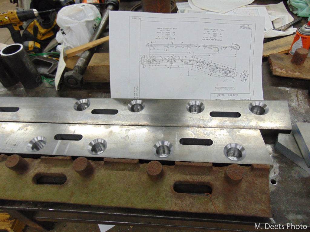
Comparison of the two mostly-complete new grate side bars versus the old side bar. A Chicago & North Western Railway drawing dated August 26, 1932 with detailed dimensions is seen in the background.
The old center support is not in horrible shape but has been modified and repaired over the years. The main web of the new center support has been tacked together to allow for fitting into the firebox. Once it had been trimmed to the proper length and height the pegs will be welded in, a plate along the bottom edge will be welded on and the bridge support pieces will be added to make a complete assembly.
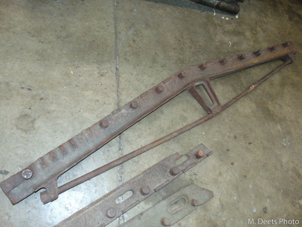
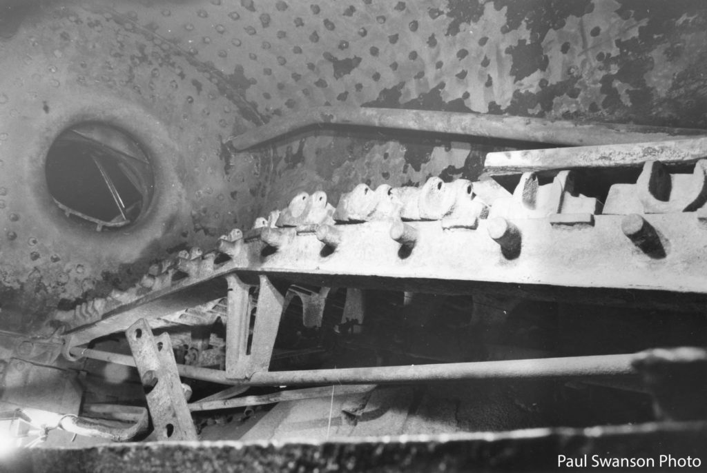
A photo from the 1990s showing the interior of 1385’s firebox with center grate bearer. The grates from the near (engineer) side have been removed and placed atop the grates on the fireman side. 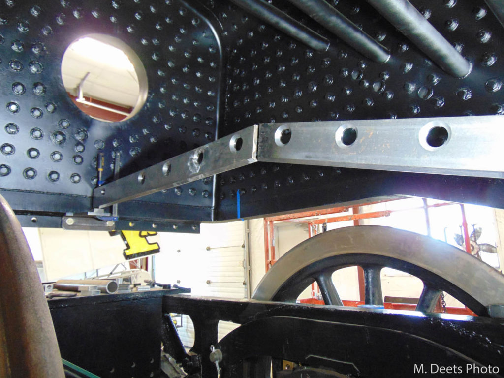
Current view of the center grate bearer being test-fitted inside the firebox. This view is looking toward the rear of the firebox. The circular cut-out is for the firedoor where coal will be shoveled into the locomotive.
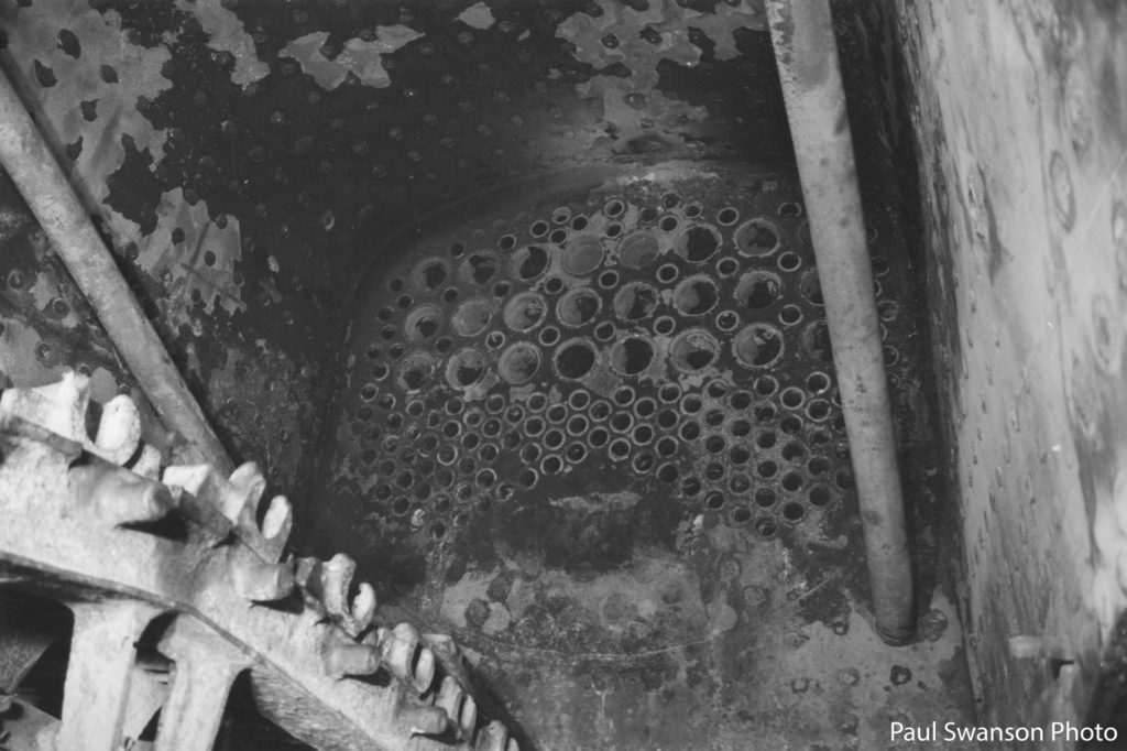
View inside C&NW #1385’s firebox looking in the direction of the rear tube sheet. Photo taken in the 1990s. 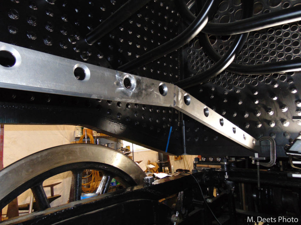
Current view looking toward the rear tube sheet and front-left corner of the firebox. The center grate bearer which runs lengthwise down the center of the firebox is shown being test-fit prior to permanent installation.
